Flashing the LED using the Zigbee protocol or the Tricolor GS SMH-ZW-I1 control module with PTVO firmware
PTVO firmware – first acquaintance.
As I already mentioned, in order to create the firmware for the CC2530 / 2531 chip for your device, you do not need to be able to program. This became possible thanks to the firmware configurator from the project ptvo.info
You can use the firmware configurator and the firmware itself for free, but in this case the functionality will be limited. In the free version, configuration of 8 inputs and 8 outputs is available (in the paid version, 16), and it is not possible to create devices with a power saving mode, which is necessary when using battery power. In the case of creating a Zigbee device based on the Tricolor control module, the free functionality is enough for the eyes.
Let’s download latest configurator and get acquainted with its functionality.

The configurator works under the Windows operating system, the program interface is quite laconic, there is support for the Russian language. The default language is English, but this can be easily fixed in the Language menu.

The firmware generator supports work with a fairly large number of sensors and actuators, allows you to memorize the state of the outputs in case of power failure and configure inputs to process single, double, triple clicks, as well as bind inputs directly to the outputs of the CC2531 chip, providing the ability to change the states of these outputs by pressing a button … The state of the inputs and outputs can also be inverted directly in the firmware.

If incorrect or unsupported options in the current configuration were selected during the configuration, the program will inform you about this.
You can learn more about the capabilities of the firmware read here, and with examples of finished devices based on it, you can read here…
We make the firmware for your device
In order to create a firmware for your device on the CC2530 / CC2531 chip, you need to specify the type of board and the type of device.

For a device based on the Tricolor control module, the “Board Type” parameter will correspond to CC2530, and the device type will depend on what we want to receive at the output. For most devices, you need to select the “Endpoint device without router function” option, but I will choose the “Router” option, as I plan to expand the Zigbee network by using a homemade device.
Now you need to configure the inputs and outputs. We arm ourselves with a multimeter, datasheet on the CC2531 chip and find which pins of the chip are brought out to convenient places on the printed circuit board. Let’s start with the pin that drives the LED. Since almost all pins of the CC2531 chip at the output can deliver a current of no more than 4mA (except for pins P1_0 and P1_0, the current of which can be up to 20mA), the LED is not connected directly to the pin, but through a transistor switch. By simple gestures with a multimeter, we find that the pin we need is the P0_4 pin. We configure it in the firmware.

The rest of the pins are configured in a similar way, but we are not interested in them yet; for our purposes, one pin is enough, on which the LED hangs. We put a tick “Remember state” if it is necessary for the state of the LED to be preserved in case of power failure and to be restored after its appearance. We save the firmware in * .hex format
Flashing the CC2531 chip. Another way.
To flash the Tricolor control module with your firmware, you must have a CC Debugger or use alternative firmware methods… I do not have a programmer, it is rather cumbersome to sew using a construction from a raspberry pi, so I used an Arduino Uno for the firmware and CCloader… But this option is also not the most convenient, because you have to convert the hex firmware to bin format using the console program, and flash it using the console program.
But there is another way to flash the CC2531 chip using VLK DIY Multi Flasher graphics program from @DJONvl and Arduino.
Downloading VLK DIY Multi Flasher, start, select the COM port on which the Arduino hangs, click Connect, and then Make Flasher. The Arduino will be flashed with the firmware necessary for the flasher to work, after which you can connect the Tricolor control module to it in accordance with the table shown.
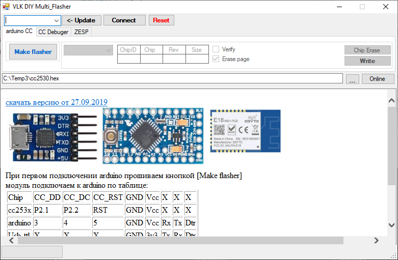
Next, you need to select the firmware obtained using the PTVO firmware configurator for our device and click Write. If you really want to, then first click Chip Erase, then Write. After a while, the chip will be flashed, rebooted and enter pairing mode. At this point, you need to allow the connection to Zigbee2MQTT and wait for our homemade device to pass the interview.
Flashing LED on MQTT
After the interview ends, a new device will appear in Zigbee2MQTT ptvo.switch
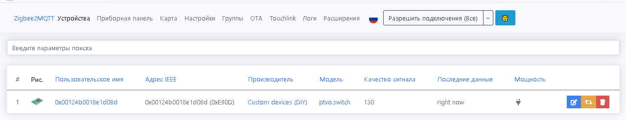

For convenience, let’s change the username to something pleasant, for example, “router”, and then see what topics Zigbee2MQTT creates in the broker for this device.

Fine! Device status can be obtained from JSON payload "state_l1", and you can control the state of the LED by sending JSON payload with the value "ON" or "OFF" to topic zigbee2mqtt/router/set
You can also control the LED from the Zigbee2MQTT web interface, but for the device ptvo.switch the interface is too congested.

The presence of unnecessary controls for a device with one LED is explained by the fact that Zigbee2MQTT cannot automatically determine which sensors, inputs and outputs are involved in the device firmware. If you want to avoid unnecessary elements in the z2m interface, you need to create a firmware with a unique identifier of the Manufacturer and Model, unload the external converter for it, and add it to Zigbee2MQTT.
Now you can fully use a homemade device as a Zigbee Router and integrate it into a Smart Home using the MQTT protocol.
Thus, you can create a Zigbee device based on the Tricolor control module, not limited to just the LED. A large number of sensors and actuators available in the PTVO firmware allow you to seriously expand the functionality by turning the Tricolor control module into a Zigbee thermometer, voltage and current sensor, volume control, switch, and so on and so forth. But this is already a topic for a new post.
Thank you very much for your attention, and creative success!