Creating a 3D model of a part from a PDF drawing

PDF file recognition
Run the nanoCAD Mechanics program. Create a new file by calling the command NEW (new): either click in the upper left corner of the screen on the nanoCAD logo and in the drop-down menu that opens, specify File -> New, or use the corresponding button on the main panel (Fig. 1).

Figure: 1. Main panel
To create a sketch, you need to upload a PDF file Lodgement.pdflocated in the archive folder. To load, call the command PDFIMPORT (pdfimport) or in the classic interface (File -> Import pdf), or in the tape (Insert -> Import -> Import PDF) and select the file Lodgement.pdf… In the dialog box Import PDF select everything shown in fig. 2, and press OK… In the command line, enter coordinates 0,0,0 and press Enter…
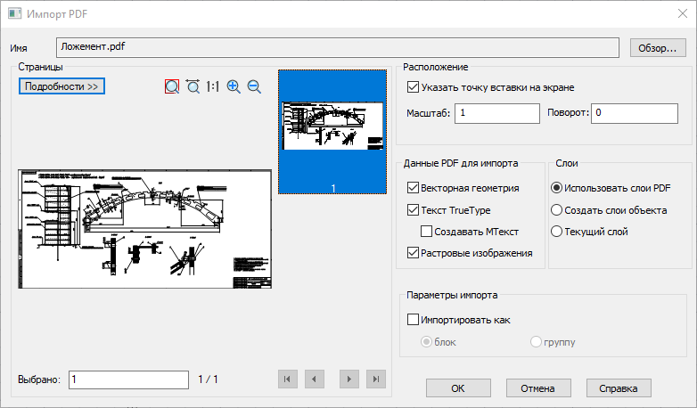
Figure: 2. Dialog box Import PDF
After that the file Lodgement.pdf will be loaded into the drawing.
Adding a flat sketch and locking the layer
To start drawing the path, you must first lock the layer and add a flat sketch. To block a layer, call the command LAYER (layers) or in the classic interface (Format -> Layer), or in the tape (Home → Layers) (fig. 3).
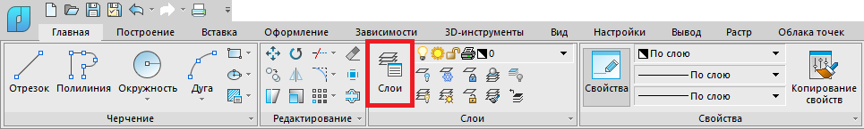
Figure: 3. Calling the command LAYER in the ribbon interface (home → Layers)
After calling the command LAYER a dialog box will open Layerswhich has a layer PDF_Geometry (fig. 4). It must be locked by clicking the left mouse button (LMB) on the icon depicting a lock. After that, the layer will be locked, and the icon will change color to gray (Fig. 5).
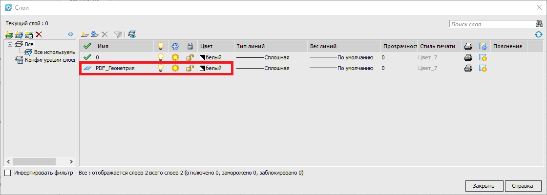
Figure: 4. Layer PDF_Geometry
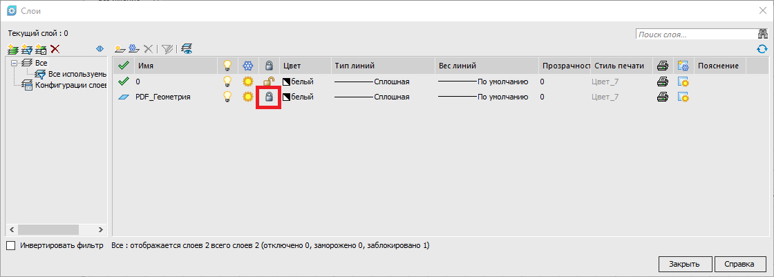
Figure: 5. Locked layer
When the layer is locked, you can start adding a flat sketch. Create a new sketch by calling the START SKETCH (psadd) command either in the classic interface (3D → 2D sketch → Add flat sketch) or in the ribbon (3D tools → 2D sketch → Add sketch) (Fig. 6).

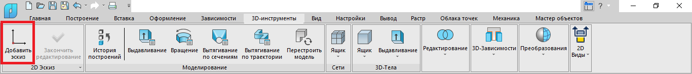
Figure: 6. Panel 3D tab… Button Add sketch… Inactive sketch mode
After that, the command line will be able to select the plane of the world coordinate system, in which the drawing will take place. Select plane XY (fig. 7)…
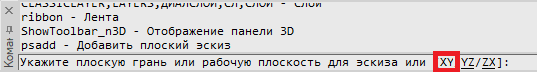
Figure: 7. Selecting a sketch plane
Further drawing is performed in sketch mode.
Drawing an outline using snaps
For more convenient drawing of the contour, you should enable snaps using the hotkey F3… The selection of the required bindings, shown in blue frame (Fig. 8), is carried out by right-clicking (RMB) on the button BONDING in the bottom panel.
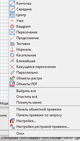
Figure: 8. Popup menu button o Snap
After all the references are selected, you can proceed to drawing a sketch along the contour of the lodgement. The sketch will be drawn using lines, arcs and circles. For this model, it is planned to draw one integral contour – this is done for simplicity and convenience, since the subsequent transformation of the contour into a 3D model will require only one operation. Also note that it is possible to create multiple sketches, which can be useful when creating more complex 3D models. The sketch of the lodgement should look like the one shown in fig. nine.
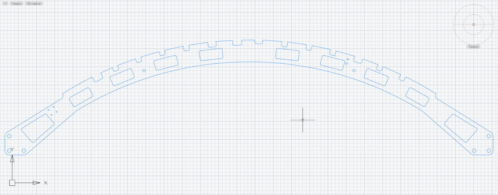
Figure: 9. Sketch of the lodgement
Do you design Mechanics in nanoCAD? Take part in the project competition – www.nanocad.ru/information/events/21362426…
After creating a sketch, you need to make the contour closed, for which you should select the entire sketch with a crossing frame (click LMB in a free space in model space → move cursor from right to left → again click LMB in a free space of the model space) and call the command COMPOUND or in the classic interface (Editing -> Connection), or in the tape (Build -> Join) (fig. 10). After that, you need to click LMB on the contour and check the closedness of the contour in the properties.
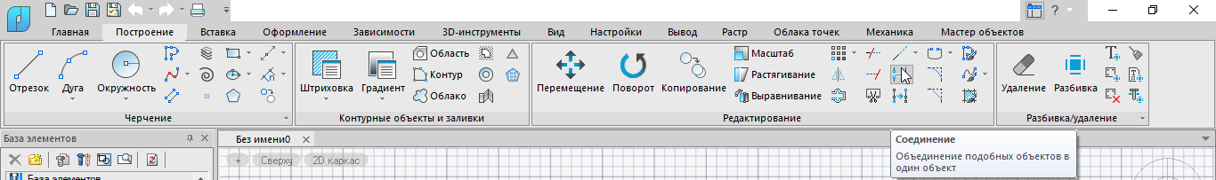
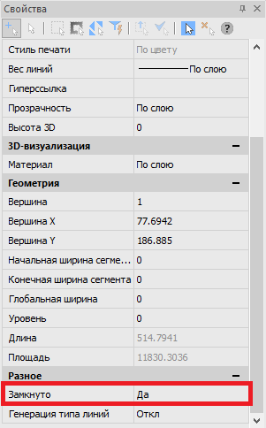
Figure: 10. Connecting the contour and checking its closedness
To edit a sketch, open the panel History of 3D Constructions and double-click on the created sketch, or right-click and select the command in the menu that opens Edit… Open the panel History of 3D Constructions you can use the command TAB_HISTORY_3D_BUILDINGS (showtab3dhistorynet) in the classic interface (3D → History of 3D Constructions) or in tape (3D Tools → Modeling → Construction History) (fig. 11).

Figure: 11. Opening the panel History of 3D Constructions
After drawing the outline, go to the dialog box Layers and turn off the layer PDF_Geometryby clicking LMB on the icon of a burning light bulb. The light will go out and the layer will be disabled (fig. 12).


Figure: 12. Disable a layer
Scale rendered sketches to their original scale
For the lodgement in the drawing, the scale is 1: 5, the scale of the sketch so far corresponds to this. To bring the scale of the sketch to the required (1: 1), you need to increase it five times using the command SCALE… To ensure correct scaling, go to sketch editing through the panel History of 3D Constructions, select the contour and call the command SCALE (scale) or in the classic interface (Editing -> Scale), or in the tape (Plot → Scale)… The command line prompts you to select a base point (enter 0,0,0 and press Enter), and then the scale (enter the number 5 and press again Enter). As a result, the sketch will be enlarged five times relative to coordinates 0,0,0 (fig. 13).

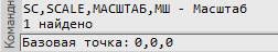
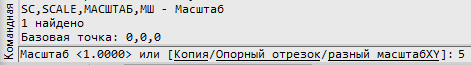
Figure: 13. Scaling
The result of the actions taken can be seen in Fig. 14, and on the Internet also when you open the file attached to this material Create sketch.dwg…
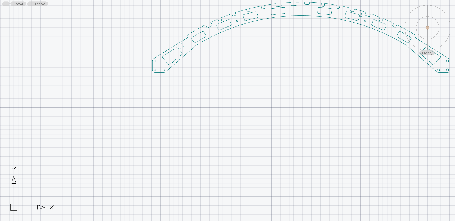
Figure: 14. Sketch of the lodgement to scale
Creating a 3D model of a part
After bringing the sketch to the original scale, you can proceed to create a 3D model. For this we will use the command Extrusion (3dextrude) by calling it either in the classic interface (3D → 3D Elements → 3D Extrude), or in the tape (3D Tools → Extrude) (fig. 15).

Figure: 15. Calling a command Extrusion
After calling the function, you will be prompted to select a sketch (Fig. 16). We select a sketch and put down the values according to Fig. 17.

Figure: 16. Sketch selection
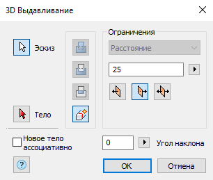
Figure: 17. Dialog box 3D Extrude
After putting down all the values, press OK… The 3D model is created, now you need to rename it and convert it to a part. To do this, go to the panel History of 3D Constructions, right-click on the object Body (1) and choose Rename… Enter the word “Lodgement” and click Enter. Right-click again on the Lodgement object and select Create part… After performing this operation, the body is transformed into a part (Fig. 18). The named part has been created.
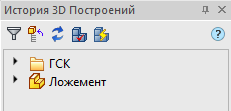
Figure: 18. Detail “Lodgment” in the panel History of 3D Constructions
In order to avoid problems associated with incorrect snapping during the further creation of the assembly of the 3D model, the “Lodgment” part must be fixed. To do this, in the panel History of 3D Constructions right-click on the “Lodgment” detail and in the menu that opens, select Fixation… An anchor icon appears in the lower right corner of the part icon (Figure 19).
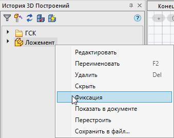
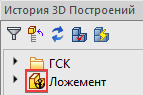
Figure: 19. Fixing the part
After fixing the part, you need to create a new User Coordinate System (UCS) with origin in the lower left corner of the part “Lodgement”. This can be done with the command PSKNEW (SetUCSByPoint). We call it either in the classic interface (Service → New UCS → Start), or in the tape (View → Coordinates → UCS, Start) (fig. 20).
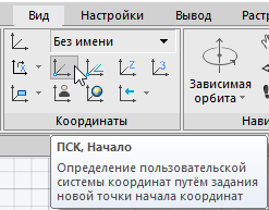
Figure: 20. Command call UCS, Start in the ribbon interface
After calling the command, select the point in the lower left corner of the “Lodgment” part (Fig. 21) and press LMB. This creates a new coordinate system associated with the part.
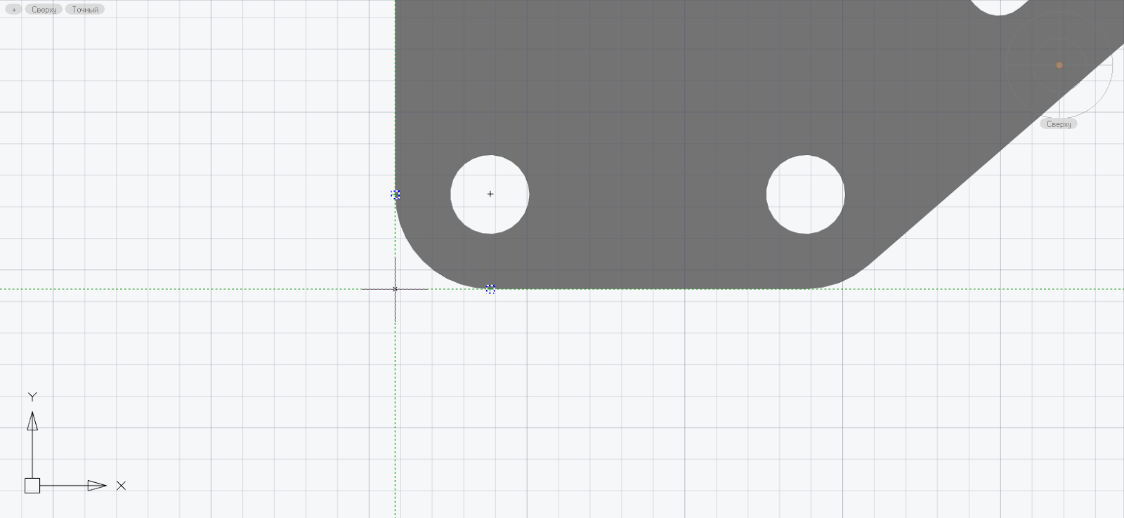
Figure: 21. New UCS
For the convenience of further work, you can change the color of the part. In the panel History of 3D Constructions double-click LMB on the “Lodgment” part, in the opened tab Block editor using LMB, select “Lodgment” in model space, go to the panel Properties and in the drop-down list select the option Color → Color selection (fig. 22). In the dialog box Color selection define the color using the palette or color number (Fig. 23) and then click OK, Save block and Close the block editor (fig. 24). Similar actions can be performed with other parts.
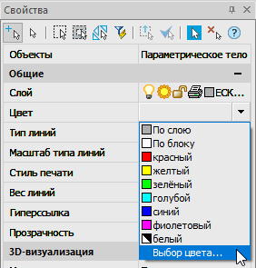
Figure: 22. Choosing a color in the panel Properties
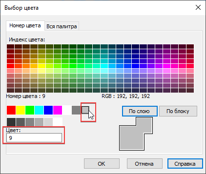
Figure: 23. Dialog box Color selection
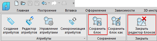
Figure: 24. Saving and closing the block editor
The result of performing the actions presented in this chapter can be seen in Fig. 25, and on the Internet also when you open the file attached to this material Creating a 3D model of the part.dwg…
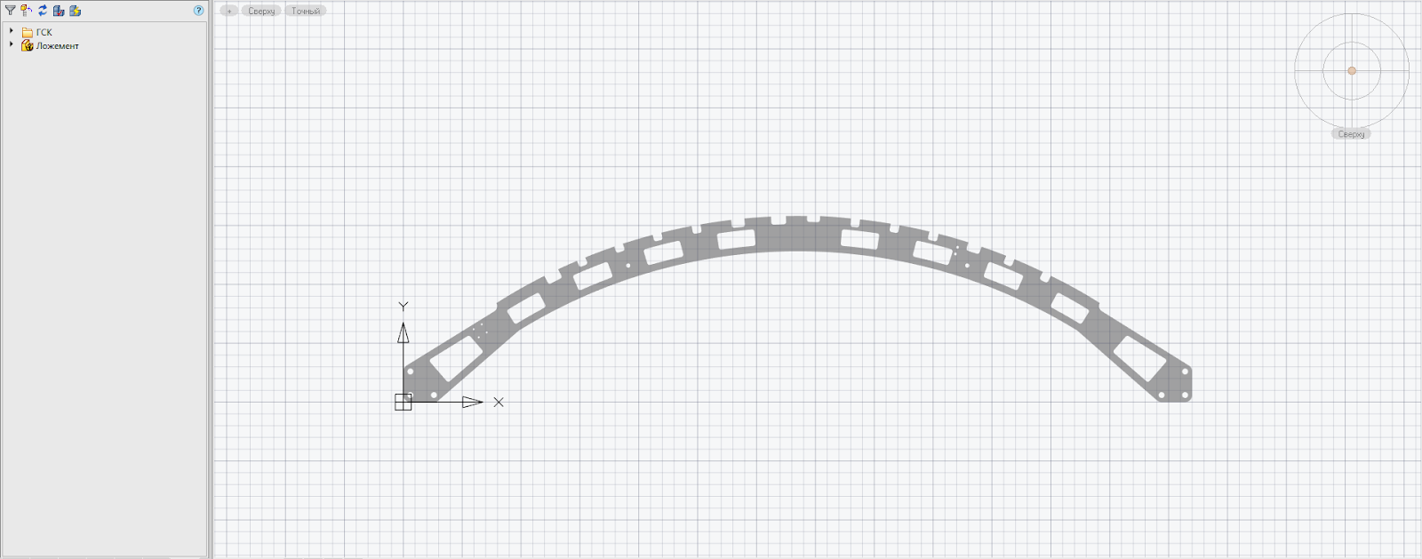
Figure: 25. Detail “Lodgement”
In the next article, we will look at creating a 3D model of an assembly based on the created 3D model of a part.
Georgy Glazkov,
Konstantin Minaev
JSC “CSoft”
E-mail: glazkov.georgiy@csoft.ru,
minaev.konstantin@csoft.ru