Create a 3D assembly model
In the previous article, we talked about creating a 3D model of a part from a PDF drawing. Let’s now consider creating a 3D model of an assembly using a previously created 3D model of a part.

Load a fastener assembly into a model
When the 3D part is created, the assembly parts must be added to the drawing. To do this, in the files, attached to this material, open the 3D Models named Fastener 1.dwg, Fastener 2.dwg, and Bushing.dwg. After opening the files, select all the parts and copy them into the drawing with the 3D model of the lodgment. To do this, in an open drawing with 3D models of assembly parts, select all models with a crossing frame and press Ctrl + C. Then go to the drawing with the 3D part “Lodgment” and press Ctrl + V to paste them into model space.
Inserting parts using the example of the file Fasteners 1.dwg is shown in Fig. 1.

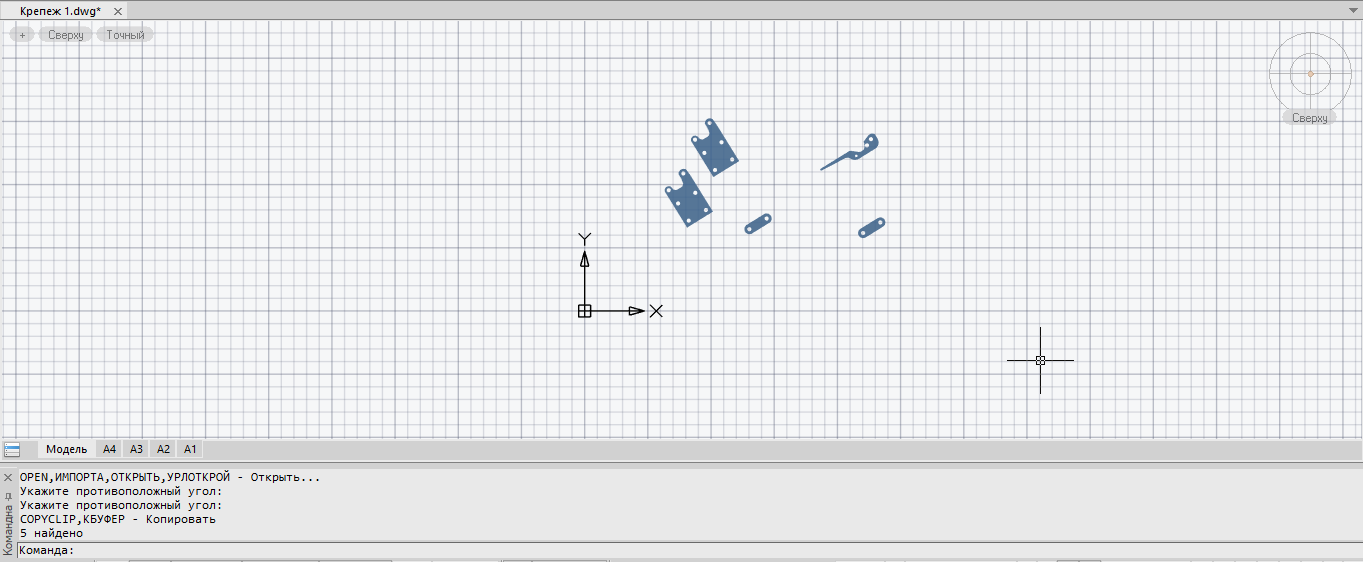
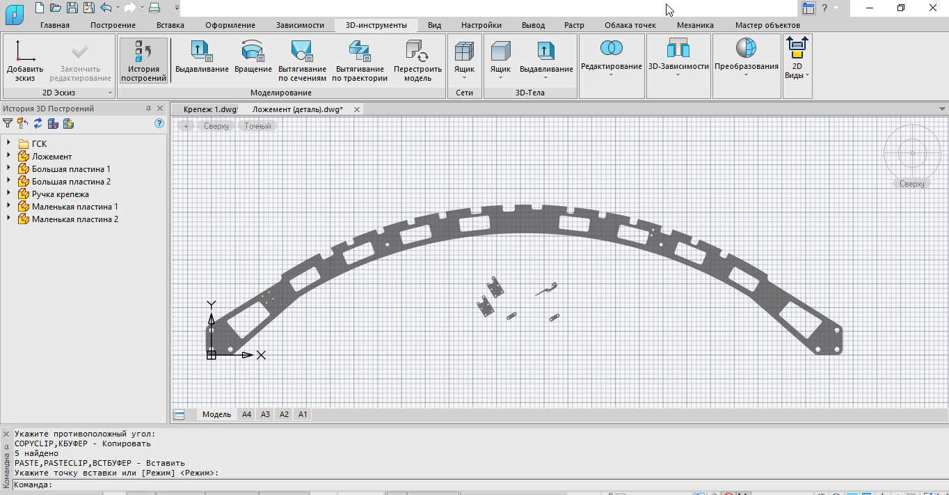
Figure: 1. Inserting parts
We perform similar actions with the rest of the details. After completing all the operations, the 3D Drawings History panel should display the structure shown in Fig. 2.

Figure: 2. Panel History 3D Constructions
Inserting 3D elements from base
After inserting all the parts into the model, you need to add elements from the base. To do this, you should either call the Element Base panel with the command TAB_BASE_ ELEMENTS (showtablibrary), or open it in the classic interface (Right-click (RMB) on the free space of the pinned tabs → Function Panels → Element Base) (Fig. 3).
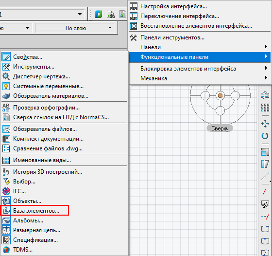
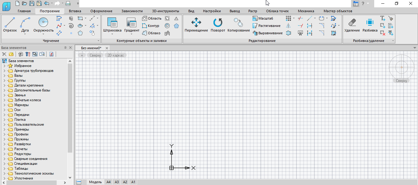
Figure: 3. Functional panel Base of elements
Further, in the Base elements panel, left-click (LMB) on the 3D model button (Fig. 4) so that the base elements are inserted exactly as 3D models.

Figure: 4. 3D model button
After that, we insert the following elements into the model space: Pin GOST 3128-70 8×35 2 version (six pieces), Pin GOST 3128-70 8×45 2 version (two pieces), Bolt M10x50 GOST 15590-70 (two pieces), Nut M10 GOST 15523 -70 (two pieces). To do this, go to the Element Base panel, open Fastening Details → General Mechanical Engineering → Pins → Cylindrical → GOST 3128-70, select the desired element and insert it using LMB. Or press the button Database search bar (Fig. 5), enter GOST 3128-70 in the line that appears and press Enter. Then, in the search window, select the part of interest to us, which will be displayed in the Base of elements panel, and insert the element into the drawing. In the opened dialog box, select the values in accordance with Fig. 6. We carry out similar operations with the rest of the elements.

Figure: 5. Base search button
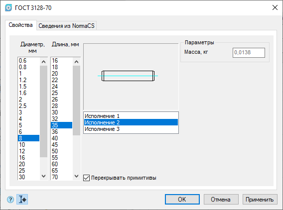
Figure: 6. Pin values
Creating a 3D thread
Let’s create a 3D thread for such base elements as Bolt M10x50 GOST 15590-70 and Nut M10 GOST 15523-70 (starting from version nanoCAD Mechanics 21.0, standard elements have their own threads). To do this, we will use the 3D thread function, which can be called either using the 3-THREAD command (3dthread), or in the classic interface (3D → 3D elements → 3D thread), or in the ribbon (3D tools tab → 3D thread) (Fig. . 7).

Figure: 7. Calling the 3D thread function
After the 3D Thread dialog box appears, select the last face of the bolt, and a thread is created on it automatically. The thread parameters will be displayed in the 3D Thread window (Fig. 8).
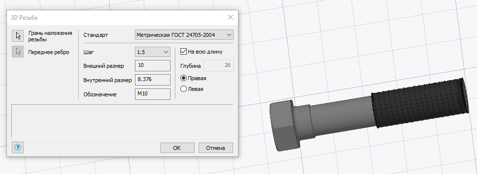
Figure: 8. 3D Carving dialog box
We perform the same actions with the rest of the elements, after which we transform all the elements into parts – in the same way as it was done in the case of the “Lodgement” part.
Inserting 3D Constraints
When all parts are inserted into model space, we need to snap them to each other, for which we will use the 3D Insert and 3D Corner functions. You can call the 3D Insert function either using the command 3ZAVE-INSERT (3dinsert), or in the classic interface (3D → 3D Elements → Constraint 3D insert), or in the strip (3D-Tools – 3D constraints – 3D insert). The Angular 3D Constraint function is called either using the command 3ZAV-ANGULAR (3dangle), or in the classic interface (3D → 3D Elements → Angular 3D Constraint), or in the strip (3D-Tools – 3D Constraints – Angular 3D Constraint) (Fig. 9 ).

Figure: 9. Calling functions 3D Insert and Angular 3D Constraint
Snapping of parts is carried out by snapping faces. After calling the function 3D Insert or Corner 3D Constraint, it is proposed to select two faces of the parts, which either must touch each other or relative to which the parts are snapped. After selecting the faces, the parts will automatically link to each other. The command line prompts you to select the direction of snapping, as well as the distance by which the parts should be spaced apart relative to the snapped faces. After snapping, if you need to make changes to the constraint, double-click LMB in the 3D Constructions History panel on the created snapping – in the command line, you will be able to specify the required parameters. If it becomes necessary to change the snap distance of the part, you can edit the snap directly from the 3D Drawings History panel. Click LMB on the anchor value – the field for editing its distance will become available. We will demonstrate below how the 3D snapping is performed (using the examples of the parts “Large plate 1” and “Fastener handle”). In order for the part to be exploded in the correct direction with respect to the snap to the lodgement when using 3D Inserts, you must select the lodgement face with the first geometry, and the face of the attached part with the second. If you need to explode parts in the opposite direction, it is possible to enter negative reference values. After calling the function, you will be prompted to select the first geometry (Fig. 10).


Figure: 10. Selecting the first geometry
To begin with, let’s look at the 3D Insert using the example of the “Large plate 1” part. We call the command and select the face of the hole in the lodgement. It will be highlighted in yellow (Fig. 11).
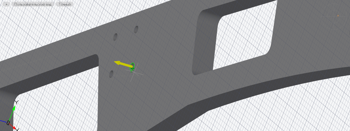
Figure: 11. Face of the hole of the “Lodgment” part
Then you will be prompted to select the second geometry (Fig. 12).

Figure: 12. Choosing a second geometry
Select the hole in the part “Large plate 1” (Fig. 13).

Figure: 13. Hole of part “Large plate 1”
Press Enter, the details are aligned and attached. If the part needs to be taken to the side, go to the 3D Drawings history panel, expand the history of the part “Big plate 1” and double-click the insert (Fig. 14) to enter the edit mode. Then enter a new value in the command line (for example, 100) and press Enter.
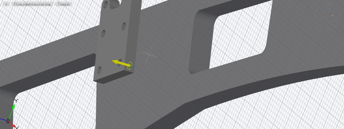
Figure: 14. Editing a 3D insert
The part will move the specified distance (Fig. 15).
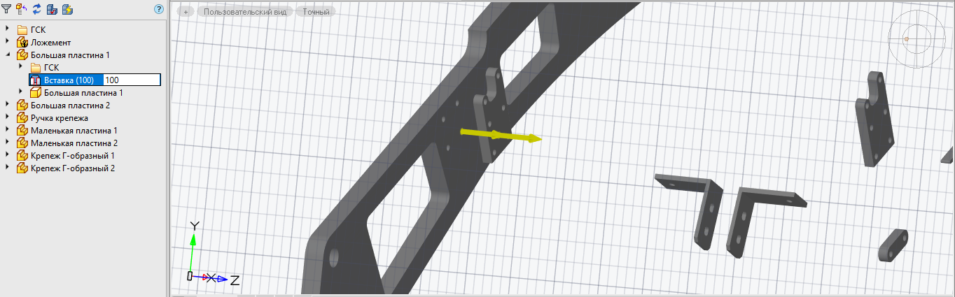
Figure: 15. Offset part
Now let’s look at the Corner 3D Constraint using the example of the “Fastener Handle” part, which is already anchored using 3D Insert to the “Large Plate” part. After calling the command, select the edge of the upper face of the Lodgement part closest to the “Fixture handle” part – it will be highlighted in yellow, the arrow will indicate the direction of the face movement (Fig. 16). After that, the program will offer to select the second geometry (Fig. 17).
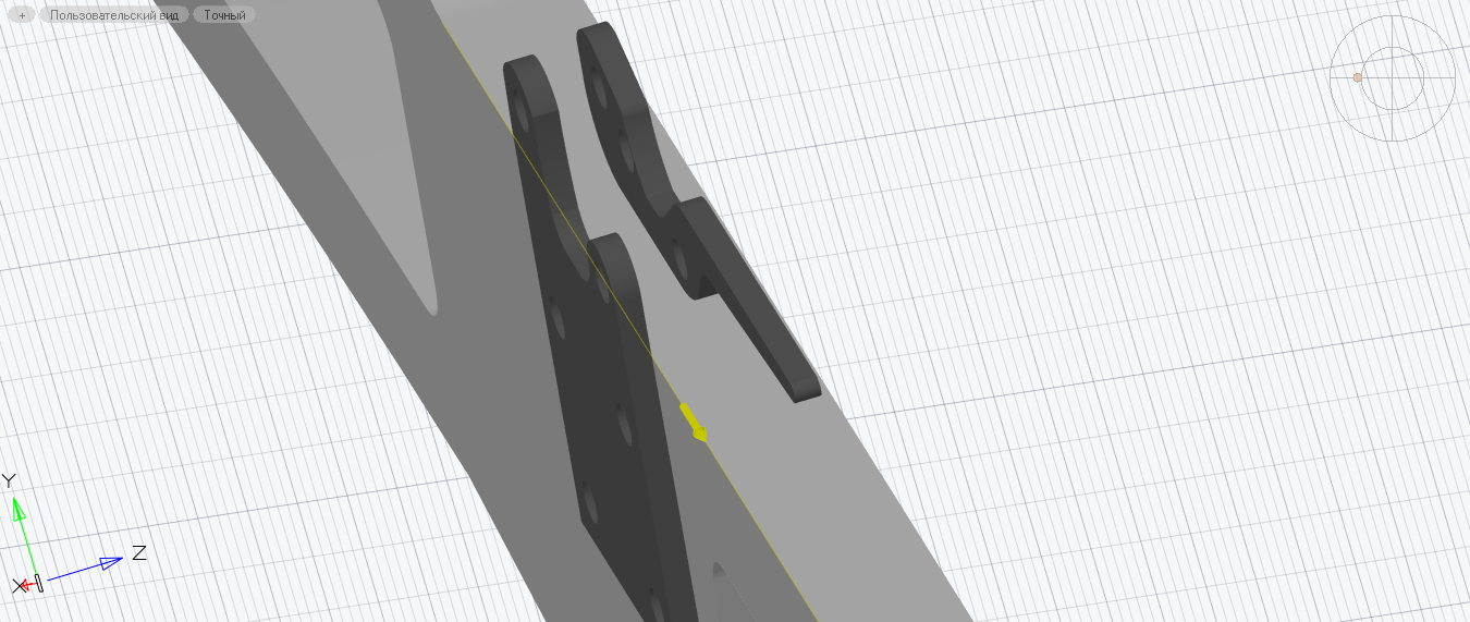
Figure: 16. The edge of the top face of the “Lodgment” part

Figure: 17. Selection of the second geometry
Select the edge on the handle of the fastener (fig. 18).
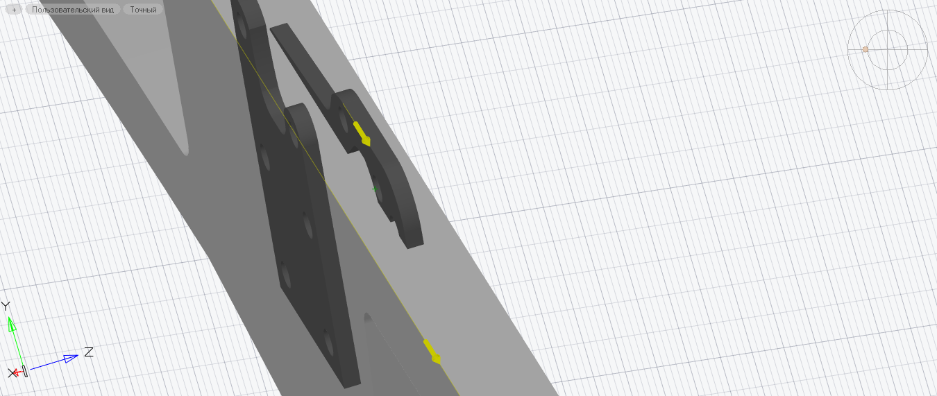
Figure: 18. Edge of the part “Fastener handle”
Because we selected bi-directional faces, the Fastener Handle part was automatically rotated to match the direction of movement of the Lodgement part face (Figure 18). To maintain the desired position, we must change the value of the anchor, expressed in degrees. Enter 180 into the command line and press Enter, after which the required angular dependence will be created. If you want to preserve the zero values of the angular references (for example, for ease of work with them), you can select co-directional faces – in this case, when previewing, the directions of their arrows will coincide. If the part needs to be rotated, go to the 3D Drawings History panel, expand the “Fixture Handle” part creation history and double-click on the angular constraint (Fig. 19) to enter the edit mode. Then enter the required value and press Enter. Note that when the part is rotated, others that are directly attached to it rotate as well.

Figure: 19. Rotate part
We perform similar actions with the rest of the details. The binding result is shown in Fig. 20.
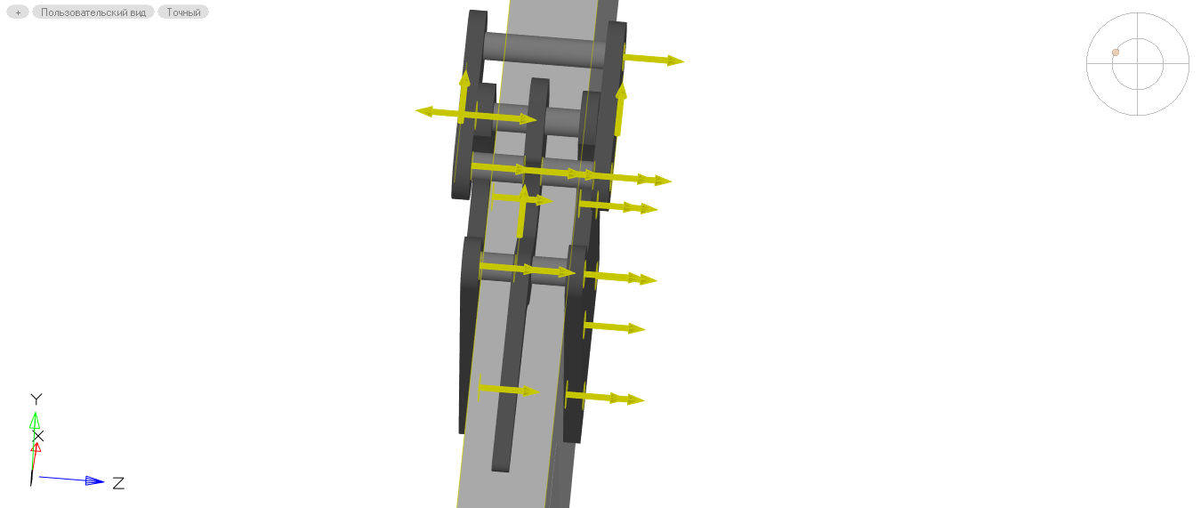

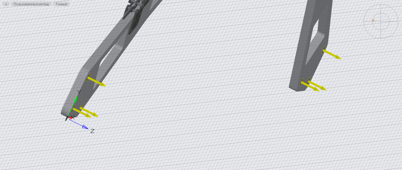
Figure: 20. Snapping parts
For the convenience of setting standard binding values, you can focus on the file Create a 3D assembly model.dwg, attached to this material and available on the internet. The final assembly result is shown in Fig. 21.
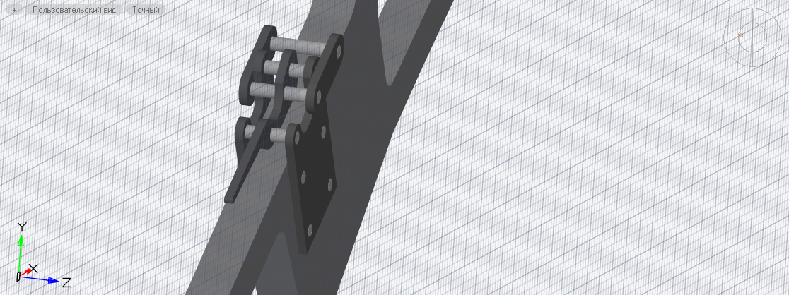
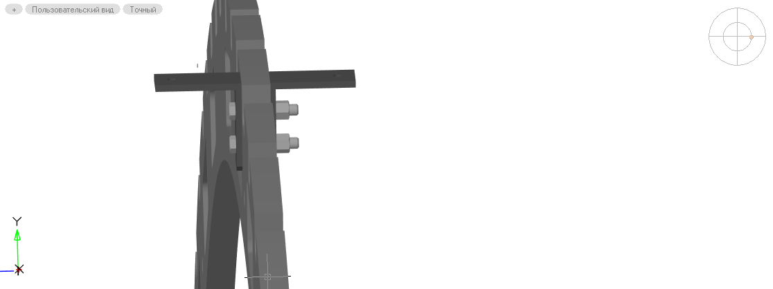
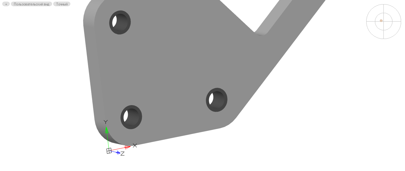
Figure: 21. Assembly “Lodgement”
In the next article we will look at the design of the assembly drawing.