Constructive assemblies in nanoCAD Constructive BIM

In version 2.0 of the nanoCAD Design BIM program, a new functionality has appeared – a constructive assembly tool, which allows you to optimize and simplify the work of the designer, especially in the case of large models.
Without putting off acquaintance with the new product indefinitely, let’s take a closer look at the operation of the tool, study its settings, and towards the end of the article I will share with you one very useful life hack …
What is constructive assembly?
Tool Constructive assembly allows you to collect individual structural elements into a new object with information parameters and a point of insertion into the project. Having created an assembly and replicated it in the drawing, in the future we can, by making changes to one of the assemblies, automatically apply them to the rest of the assembly occurrences.
The main command for working with structural assemblies is the command Create structural assembly (AEC_ASSEMBLY). Its location in the interface is shown in Fig. 1.
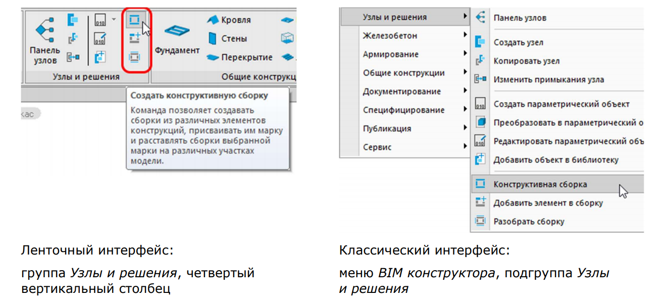
Figure: 1. Location of commands in the interface
The AEC_ASSEMBLY command invokes a dialog Structural assemblies, which allows you to create new assemblies, maintain a list of assemblies represented in the model, quickly find all occurrences of the assembly in the model, as well as place new assemblies, delete them, and perform other operations (Figure 2).
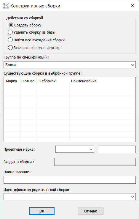
Figure: 2. Structural Assemblies Dialog Box
The dialog also has a field Specification group, where from the drop-down list you can choose one of the existing options or specify your own.
A list of assemblies previously created in a specific BOM group will be displayed under Existing assemblies in the selected group:…
Project brand – alphanumeric designation of the assembly;
Included in assemblies – the field where the design mark of assemblies is displayed, which will include the assembly selected from the list;
Name – indicates the name that we want to set for the assembly;
Parent assembly ID – indicates the identifier of the assembly, in which it is planned to include the newly created assembly.
What parameters does the assembly have and what parameters are important for the elements included in it?
Build an assembly
To make the most of the program’s capabilities, it is important that all the elements in the drawing not only have a “physical” representation, but also have certain informational parameters. The more carefully the information component is worked out, the more efficiently we can generate the necessary documentation (2D views, drawings and specifications).
Let’s take a concrete example to see what information parameters are important for structural assemblies. As an example, let’s take a columnar foundation with reinforcing bars and anchor bolts (Fig. 3).
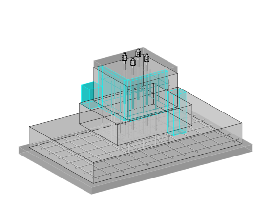
Figure: 3. Column foundation
We call the command Create structural assembly (AEC_ASSEMBLY) opens a dialog box Structural assemblies… Choose an item Create assembly and specify the following parameters:
- Specification group – Monolithic foundations;
- Project brand – FM1;
- Name – Foundation FM1.
Click OK and, following the program prompts, create an assembly: select the objects that we want to place in it, indicate the base point of the assembly (later on it will be the insertion point for new assemblies and “handles” for moving and rotating the object), and then set the direction of the axes coordinates.
The command line displays the message: “Assembly FM1 has been successfully created in the Monolithic foundations group.”
Let’s open the properties of the newly created assembly (Fig. 4).
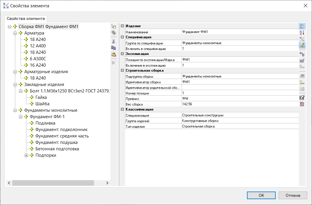
Figure: 4. Assembly properties
On the left, in the properties window, the composition of the assembly is displayed – it is presented as a tree of subordinate elements. The properties of the assembly as an object are shown on the right. In addition to the parameters we are familiar with, a section of parameters “Building assembly” has appeared, where information only about the assembly is collected.
Let’s look at the principle by which elements are grouped in a tree.
We see four sections of the first level: “Rebar”, “Reinforcement products”, “Embedded products” and “Monolithic foundations”.
The section name corresponds (in order of importance of the parameter) to the subgroup of the assembly from the section “Building assembly”, and if the parameter is not specified, then the group according to the specification and / or the group for the explication of the elements included in it.
As you can see in the assembly structure, almost all reinforcing bars are combined into the “Reinforcement” section, and only for item 18 A240, the section “Reinforcement products” is indicated. Let’s see why this happened.
If we carefully consider the properties of this rod, we will see that the value Reinforcement products specified in its parameter Specification group (parameter Assembly subgroup in this case it is empty) – that is why it was placed in a separate section (Fig. 5).
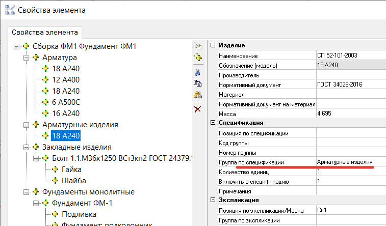
Figure: 5. Rebar properties
To avoid any inaccuracies in the assembly specification in the future, we will change Specification group of this bar by the value Armature… This can be done directly in the assembly properties window.
We will return to the conversation about the importance of the uniformity of information parameters at the stage of specification …
An options section is also added to each item in the assembly. Building assembly with a set of fields Parent assembly ID and Position number… Subsequently, these parameters will allow filtering the selection of objects for specification.
I would like to draw your attention to one more parameter that will be important for us at the stage of specification: Assembly subgroup… For objects included in an assembly, I recommend setting this parameter before the assembly is assembled. And for this, you need to at least roughly think over which section of the specification you will need to place this or that element. However, let’s come back to this topic a little later when we begin to take a closer look at the structural assembly specification.
Editing an assembly
To make any more significant changes to the structure of the assembly or to the properties of its constituent elements, you must edit the assembly. This operation is performed according to the following algorithm: parse one of the occurrences of the assembly – make changes – rebuild the assembly under the same name.
For example, you need to remove one of the anchor bolts. To do this, select the assembly of interest to us in the drawing field (if there are several identical assemblies, select one of the assembly inclusions) and call the command Disassemble a structural assembly (AEC_ASSEMBLY_DISASSM) – fig. 6.
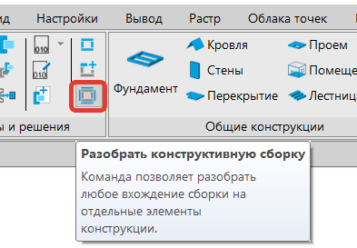
Figure: 6. Location of the Expand structural assembly command
Then we make the necessary changes to the disassembled assembly (both in the “physical” and in the informational parameters). After that we call the command again Create structural assembly (AEC_ASSEMBLY). In the opened dialog box Structural assemblies select item Create assembly, in the list of existing assemblies, select the one to which the changes were made, and click OK. Leave the design brand and assembly name unchanged (Fig. 7). Click OK.
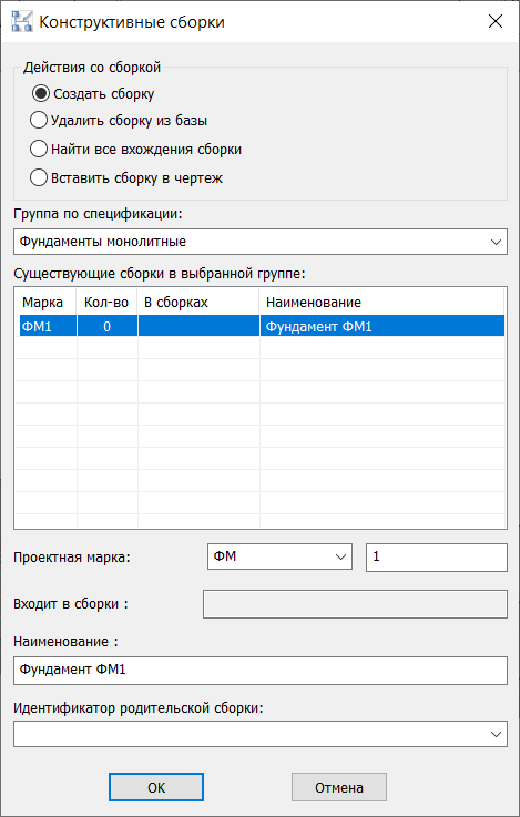
Figure: 7. Dialog Structural Assemblies during editing
The program issues a warning that this assembly is already in the drawing, and asks if we are sure that we want to rebuild it (Fig. 8). Push OK, and then we perform the actions already familiar to us to create an assembly, namely, we indicate the objects that should fall into the assembly, the base point and the direction of the axes.
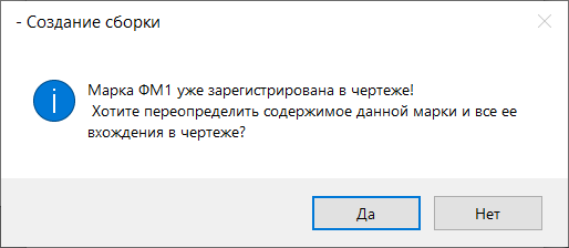
Figure: 8. Assembly override warning
The assembly was successfully edited and the changes we made applied to all of its occurrences in the drawing.
Assembly specification
Setting specification parameters and displaying them is certainly a topic for a large and separate article (or a webinar that was held on the first version of the product: www.youtube.com/watch?v=JgyCJDJYZ1o&list=PLaWJ5dzYEDotv6ufwDmBpkDXwpPcb7htW&index=20, as well as within the online school already based on the second version: www.youtube.com/watch?v=aSNjY89YtGw&t=2924s).
You can see one of the examples and possible options for specifying assemblies in the file from the Sample folder nBIM. KM model, specification profile Specification for a structural element (QOL, assembly)…
Let’s get back to talking about the importance of the parameter Assembly subgroup… Roughly speaking, we will use this parameter in order to create a section in the specification where the assembly item will belong. Of course, the parameter could be used for this Specification group, but there are situations in which it is necessary that these parameters were different (for example, when the same assembly must be taken into account in different types of BOMs).
Here is an example from one of our pilot projects. There is an assembly of the frame column, consisting of an I-beam, several metal plates and a column base, which in turn also consists of plates. The information from this column needs to be compiled into two specifications:
- product specification, where the components of our column-assembly will be presented;
- steel consumption sheet, where the elements that make up the assembly should be distributed by type, and not by belonging to any assembly.
And in this case, the parameter will help us a lot Assembly subgroup… For the elements included in the Column assembly, we will indicate the assembly subgroup Frame column, and we will indicate the specification group for each element in accordance with the section where it should go in the sheet of steel consumption. For example, for one of the plates we get the following values: Specification group – Metal plates; Assembly Subgroup – Framing Column (fig. 9).
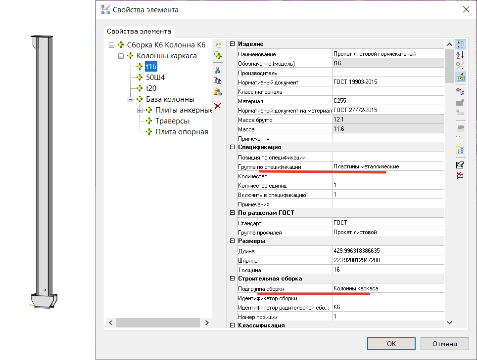
Figure: 9. Properties of the plate in the assembly Column K6
Such information parameters will allow us to easily create both required specifications.
In addition, I would like to once again focus your attention on how important it is to maintain uniformity of information parameters for the elements included in the assembly. Since if the same parameter Assembly subgroup for one of the elements, determine how Frame columnsand for the other as Frame column (i.e. use plural and singular), they will be collected in different sections of the specification. Or one of the elements will not be included in the specification at all – if earlier, for example, we indicated in the selection condition that an object with a parameter Frame column not taken into account.
Another point that we may encounter when specifying assemblies is counting the number. For example, in our drawing there are several assemblies of the same type and we need to make two specifications, one of which will take into account the total number of elements in all assemblies, and the second only one of the occurrences of the assembly. Here it’s time to share with you the promised life hack, namely the team object.isMasterAssemblyReference () <> 0…
More precisely, this is a filter that needs to be added to the object selection condition in the Specification Wizard (Fig. 10). It only counts one of all occurrences of the assembly, and you can be sure that you are specifying one unique object, and not all of its occurrences in the drawing.
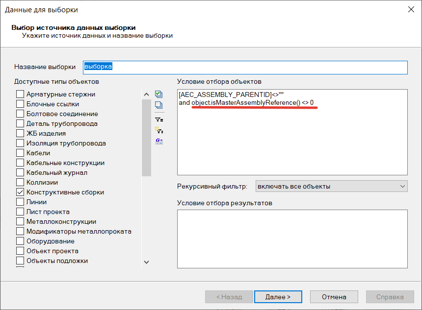
Figure: 10. Specification Wizard window
By and large, the specification of structural assemblies does not cause any problems, provided that all information parameters of the elements that make up the assembly were set uniformly and correctly, and the specification was adjusted in accordance with these parameters.
Summing up
Structural assemblies are new functionality that provides great opportunities for working with the model and specification, but at the same time requires serious attention to the information component (as, indeed, any tool in BIM design).
It is likely that you will spend more time initially setting up the correct information parameters for the objects in an assembly than if you were using them individually. However, once you get the hang of it, understand the logic and how these parameters work, your productivity will increase. It will become more convenient to edit the model, because you no longer have to worry about an object being lost in model space when making changes. The speed and convenience of preparing specifications will also be greatly improved.
And I would like to conclude this review with the words of the American journalist, writer and psychologist Napoleon Hill: “Mastery comes only with practice and cannot appear only through reading instructions.”…
Therefore, I urge you, without delay, to start using a new tool, improve your professional skills, as well as share your successes, ask questions and leave your wishes on our forum at forum.nanocad.ru…
Tatiana Tolstova,
Technical Specialist