Connecting the LCD1602 (HD44780) liquid crystal display to the ATmega8 microcontroller in 4-bit mode
Note:
The article is not an original translation. The article was created on the basis of the article (see the source of information indicated below) by translating it, using the main text of the original and supplemented by the author; This code has been tested on a real device f. winstar.
LCD displays (Liquid Crystal Displays) are used to display status or parameters in various devices.
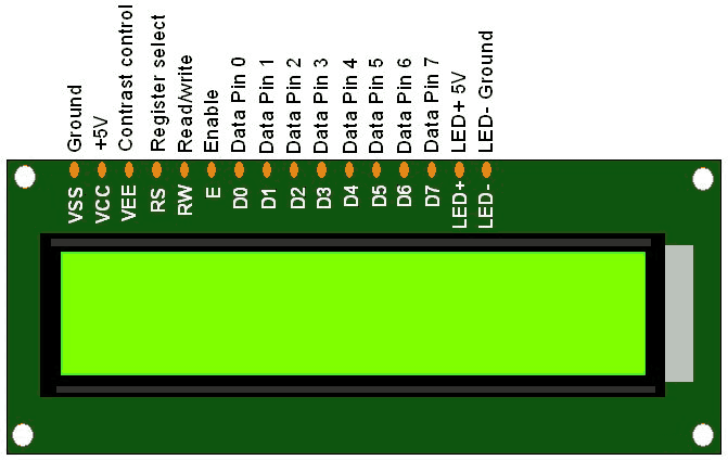
The LCD1602 is a 16-pin device with 8 data pins (D0-D7) and 3 control pins (RS, RW, EN). The remaining 5 pins are for power supply and LCD backlight. The numbers “1602” indicate the format of the output (displayed) information: 16×02 characters (Figure 1).
The control pins help us set up the LCD display in command mode or data transfer mode. They also help you set the read or write mode and the read or write time.
The 16×2 LCD can be used in 4-bit or 8-bit mode depending on the specification. In order to use it, we need to send certain commands to the LCD in command mode, and once the LCD is configured according to our requirements, we can send the necessary data in data mode.
In 4-bit mode, data/commands are sent in 4-bit (nibble) format.
To do this, you must first send the “higher” (upper) 4 bits, and then send the “lower” (lower) 4 bits of data / commands.
Only 4 data pins (D4 – D7) of the 16×02 LCD display are connected to the microcontroller, and the other control pins RS (register select), RW (read / write), E (enable signal) are connected to other GPIO pins of the microcontroller (Figure 2).
Thus, thanks to this connection, we can save four GPIO pins of the microcontroller, which can be used for other purposes.
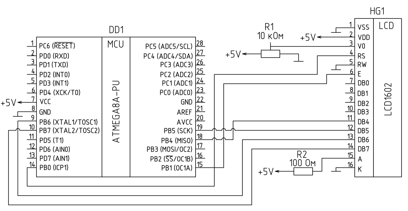
Trimmer resistor R1 is designed to fine-tune the contrast of the display. Resistor R2 is designed to limit the current at the anode of the display backlight.
Display initialization function:
1. Must wait at least 15ms power-on initialization time for LCD1602.
2. Send command 0x02, which initializes the 16×2 LCD in 4-bit mode.
3. Send command 0x28, which sets the LCD display to 2-line, 4-bit mode and 5×8 dots.
4. Send one of the display cursor enable commands (0x0E, 0x0C).
5. Send command 0x06 (move the cursor to the right).
Code Listing:
void LCD_Init (void)  /* LCD Initialize function */
{
	LCD_Dir = 0xFF;		/* Make LCD port direction as o/p */
	_delay_ms(20);		/* LCD Power ON delay always >15ms */

	LCD_Command(0x02);	/* Send for 4 bit initialization of LCD  */
	LCD_Command(0x28);	/* 2 line, 5*7 matrix in 4-bit mode */
	LCD_Command(0x0c);	/* Display on cursor off */
	LCD_Command(0x06);	/* Increment cursor (shift cursor to right) */
	LCD_Command(0x01);	/* Clear display screen */
	_delay_ms(2);
}
We have now successfully initialized the LCD and it is ready to accept data in 4-bit (nibble) mode for display.
To send a command/data to a 16×02 LCD, we must send the “high” (top) nibble and then the “low” (low) nibble. Since the D4-D7 pins of the 16×02 LCD are wired as data pins, we must shift the low nibble to the right by 4 before transmitting.
Function of writing commands (instructions):
1. Let’s send the “higher” command nibble first.
2. Set the “low” level on the RS pin, RS=0 (command register)
3. Set the RW pin to “low” level, RW=0 (write operation) or connect it to ground.
4. Give a pulse from “high” to “low” when turned on (E).
5. Let’s send the “low” command nibble.
6. Give a pulse from “high” to “low” when turned on (E).
Code Listing:
void LCD_Command( unsigned char cmnd )
{
	LCD_Port = (LCD_Port & 0x0F) | (cmnd & 0xF0);/* Sending upper nibble */
	LCD_Port &= ~ (1<<RS);		/* RS=0, command reg. */
	LCD_Port |= (1<<EN);		/* Enable pulse */
	_delay_us(1);
	LCD_Port &= ~ (1<<EN);
	_delay_us(200);
	LCD_Port = (LCD_Port & 0x0F) | (cmnd << 4);/* Sending lower nibble */
	LCD_Port |= (1<<EN);
	_delay_us(1);
	LCD_Port &= ~ (1<<EN);
	_delay_ms(2);
}
Data recording function:
1. Let’s send the “higher” nibble of data first.
2. Set RS pin to “high” level, RS=1 (data register)
3. Set the RW pin to “low” level, RW=0 (write operation) or connect it to ground.
4. Give a pulse from “high” to “low” when turned on (E).
5. Let’s send the “low” nibble of data.
6. Give a “pulse” from “high” to “low” when turned on (E).
Code Listing:
void LCD_Char( unsigned char data )
{
	LCD_Port = (LCD_Port & 0x0F) | (data & 0xF0);/* Sending upper nibble */
	LCD_Port |= (1<<RS);  /* RS=1, data reg. */
	LCD_Port|= (1<<EN);
	_delay_us(1);
	LCD_Port &= ~ (1<<EN);
	_delay_us(200);
	LCD_Port = (LCD_Port & 0x0F) | (data << 4);  /* Sending lower nibble */
	LCD_Port |= (1<<EN);
	_delay_us(1);
	LCD_Port &= ~ (1<<EN);
	_delay_ms(2);
}
Program listing:
#define F_CPU 8000000UL			/* Define CPU Frequency e.g. here 8MHz */
#include <avr/io.h>			/* Include AVR std. library file */
#include <util/delay.h>			/* Include Delay header file */

#define LCD_Dir  DDRB			/* Define LCD data port direction */
#define LCD_Port PORTB			/* Define LCD data port */
#define RS PB0				/* Define Register Select pin */
#define EN PB1 				/* Define Enable signal pin */


void LCD_Command( unsigned char cmnd )
{
	LCD_Port = (LCD_Port & 0x0F) | (cmnd & 0xF0); /* sending upper nibble */
	LCD_Port &= ~ (1<<RS);		/* RS=0, command reg. */
	LCD_Port |= (1<<EN);		/* Enable pulse */
	_delay_us(1);
	LCD_Port &= ~ (1<<EN);

	_delay_us(200);

	LCD_Port = (LCD_Port & 0x0F) | (cmnd << 4);  /* sending lower nibble */
	LCD_Port |= (1<<EN);
	_delay_us(1);
	LCD_Port &= ~ (1<<EN);
	_delay_ms(2);
}


void LCD_Char( unsigned char data )
{
	LCD_Port = (LCD_Port & 0x0F) | (data & 0xF0); /* sending upper nibble */
	LCD_Port |= (1<<RS);		/* RS=1, data reg. */
	LCD_Port|= (1<<EN);
	_delay_us(1);
	LCD_Port &= ~ (1<<EN);

	_delay_us(200);

	LCD_Port = (LCD_Port & 0x0F) | (data << 4); /* sending lower nibble */
	LCD_Port |= (1<<EN);
	_delay_us(1);
	LCD_Port &= ~ (1<<EN);
	_delay_ms(2);
}

void LCD_Init (void)			/* LCD Initialize function */
{
	LCD_Dir = 0xFF;			/* Make LCD port direction as o/p */
	_delay_ms(20);			/* LCD Power ON delay always >15ms */

	LCD_Command(0x02);		/* send for 4 bit initialization of LCD  */
	LCD_Command(0x28);              /* 2 line, 5*7 matrix in 4-bit mode */
	LCD_Command(0x0c);              /* Display on cursor off*/
	LCD_Command(0x06);              /* Increment cursor (shift cursor to right)*/
	LCD_Command(0x01);              /* Clear display screen*/
	_delay_ms(2);
}


void LCD_String (char *str)		/* Send string to LCD function */
{
	int i;
	for(i=0;str[i]!=0;i++)		/* Send each char of string till the NULL */
	{
		LCD_Char (str[i]);
	}
}

void LCD_String_xy (char row, char pos, char *str)	/* Send string to LCD with xy position */
{
	if (row == 0 && pos<16)
	LCD_Command((pos & 0x0F)|0x80);	/* Command of first row and required position<16 */
	else if (row == 1 && pos<16)
	LCD_Command((pos & 0x0F)|0xC0);	/* Command of first row and required position<16 */
	LCD_String(str);		/* Call LCD string function */
}

void LCD_Clear()
{
	LCD_Command (0x01);		/* Clear display */
	_delay_ms(2);
	LCD_Command (0x80);		/* Cursor at home position */
}

int main()
{

	LCD_Init();			/* Initialization of LCD*/

	LCD_String("Hello World");	/* Write string on 1st line of LCD*/
	LCD_Command(0xC0);		/* Go to 2nd line*/
	LCD_String("4 bit");	/* Write string on 2nd line*/
	while(1);
}
For ease of use, we will arrange the code described above as a library. To do this, we will create two files LCD1602.h and LCD1602.c.
Listing of LCD1602.h file
#ifndef LCD1602_H_
#define LCD1602_H_

#define LCD_Dir  DDRB
#define LCD_Port PORTB
#define RS PB0
#define EN PB1

#include <avr/io.h>
#include <util/delay.h>

void LCD_Command( unsigned char cmnd );
void LCD_Char( unsigned char data );
void LCD_Init (void);
void LCD_String (char *str);
void LCD_String_xy (char row, char pos, char *str);
void LCD_Clear();

#endif /* LCD1602_H_ */
Listing of LCD1602.c file
#include "LCD1602.h"

void LCD_Command( unsigned char cmnd )
{
	LCD_Port = (LCD_Port & 0x0F) | (cmnd & 0xF0);
	LCD_Port &= ~ (1<<RS);
	LCD_Port |= (1<<EN);
	_delay_us(1);
	LCD_Port &= ~ (1<<EN);

	_delay_us(200);

	LCD_Port = (LCD_Port & 0x0F) | (cmnd << 4);
	LCD_Port |= (1<<EN);
	_delay_us(1);
	LCD_Port &= ~ (1<<EN);
	_delay_ms(2);
}


void LCD_Char( unsigned char data )
{
	LCD_Port = (LCD_Port & 0x0F) | (data & 0xF0);
	LCD_Port |= (1<<RS);
	LCD_Port|= (1<<EN);
	_delay_us(1);
	LCD_Port &= ~ (1<<EN);

	_delay_us(200);

	LCD_Port = (LCD_Port & 0x0F) | (data << 4);
	LCD_Port |= (1<<EN);
	_delay_us(1);
	LCD_Port &= ~ (1<<EN);
	_delay_ms(2);
}

void LCD_Init (void)
{
	LCD_Dir = 0xFF;
	_delay_ms(20);

	LCD_Command(0x02);
	LCD_Command(0x28);
	LCD_Command(0x0c);
	LCD_Command(0x06);
	LCD_Command(0x01);
	_delay_ms(2);
}


void LCD_String (char *str)
{
	int i;
	for(i=0;str[i]!=0;i++)
	{
		LCD_Char (str[i]);
	}
}

void LCD_String_xy (char row, char pos, char *str)
{
	if (row == 0 && pos<16)
	LCD_Command((pos & 0x0F)|0x80);
	else if (row == 1 && pos<16)
	LCD_Command((pos & 0x0F)|0xC0);
	LCD_String(str);
}

void LCD_Clear()
{
	LCD_Command (0x01);
	_delay_ms(2);
	LCD_Command (0x80);
}
To connect the library, you need to place the LCD1602.h and LCD1602.c files in the project folder, in the Atmel Studio program, right-click on the project name, select Add – Existing Item, find and select all two files, click OK.
Next, we write the code:
#include <avr/io.h>
#include "LCD1602.h"

int main()
{
	LCD_Init();
	LCD_String("Hello World");
	LCD_Command(0xC0);
	LCD_String("4 bit");

	while(1)
    {

    }
}
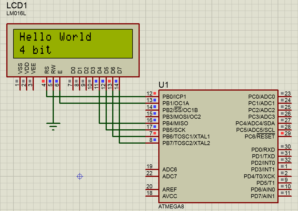
After downloading the firmware, we will see the following result on the LCD1602 display as shown in Figure 3.
The decoding of the most commonly used commands sent from the microcontroller to the LCD1602 (HD44780) display is shown in tables 1, 2.
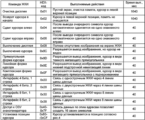
Command execution times are approximate. It is determined by the frequency of the internal RC-oscillator of the LCD display, which, in turn, depends on the technological dispersion and the temperature of the case heating.

A source of information:
https://www.electronicwings.com/avr-atmega/interfacing-lcd-16×2-in-4-bit-mode-with-atmega-16-32-


