Configuring FDCAN in CubeMx
0. The setting was made for STM32H743 with a CPU frequency of 480 MHz and an FDCAN frequency of 120 MHz


1. In order to open the FDCANx settings, there is the following path: “Connectivity” -> “FDCANx” -> “Activated”

2. Description of basic settings
Frame Format:
Classic Mode – Standard size identifier (ID) will be used.
FD mode without BitRate Switching – the extended identifier will be used without changing the data transfer rate.
FD mode with BitRate Switching – an extended identifier will be used and different transfer rates will be allowed for data bytes (green hexagons) and information bytes (all others). (As I understand it, you can set the data byte transfer rate, for example, to 100KB / s, and all other bytes to 500KB / s, or vice versa).

Mode:
Normal mode – data is sent to and read from the bus.
Restricted operation – data is received from the bus, acknowledgment signals can be sent.
Bus monitoring mode – data is only received from the bus and nothing is sent to the bus.
Internal LoopBack mode – data is not sent to the bus, but sent to the CAN input (closing is done by hardware, you don’t need to close anything yourself). Only the data sent by us is accepted, reading from the bus is not performed.
External LoopBack mode – data is sent both to the bus and to the CAN input (closing is done by hardware, you don’t need to close anything yourself). Only the data sent by us is accepted, reading from the bus is not performed.
I made such a picture for myself, BUT from the Reference manual, I could not fully understand the Restricted operation, so the picture may not be accurate (correct in the comments).

Auto Retransmission – Allows or denies messages being resent.
Transmit Pause – additional pause during transmission. This pause is necessary to give other transmitters access to the bus if their priority is low.
Protocol Exception – resolving the Protocol Exception event. During normal operation, the FDF bit must be followed by a reserved dominant (LOW) bit (res). This event is generated when the reserved bit is recessive (HIGH).
Nominal Sync Jump Width – the number of time slices of the extension, determines the allowable extension of the boundaries of bit segments “Nominal Time Seg1(2)”.
Data Prescaler – a divider for setting the frequency of transmission of data bytes (green hexagons).
Only relevant when Frame Format – FD mode with BitRate SwitchingData Sync Jump Width – the number of time slices of the expansion, determines the allowable expansion of the boundaries of the bit segments “Data Time Seg1 (2)”
Only relevant when Frame Format – FD mode with BitRate SwitchingData Time Seg1 / Seg2 – number of time slices in bit segment 1 / 2
Only relevant when Frame Format – FD mode with BitRate SwitchingMassage Ram Offset – Specifies the start address of the RAM message.
Std Filters Nbr – allowed number of filters with a standard identifier.
Ext Filters Nbr – allowed number of filters with extended ID.
Rx Fifo0/1 Elmts Nbr – number of input elements FIFO0/1 (Place where received data is stored).
Rx Fifo0/1 Elmts Size – size in bytes of FIFO0/1 input elements.
Rx Buffers Nbr – the number of input buffers (The place where the received data is stored).
Rx Buffer Size – size in bytes of RxBuffer input buffers.
Tx Events Nbr – ??? (I didn’t figure it out myself, I think the comments will prompt).
Tx Buffers Nbr – number of buffers for sent messages.
Tx Fifo Queue Elmts Nbr – the size of the queue that stores messages ready to be sent.
Tx Fifo Queue Mode – transmit buffer operation mode:
Fifo Mode – Fifo buffer.
Queue Mode – queue mode.
Tx Elmt Size – size of sent messages in bytes.
My basic settings are as follows.

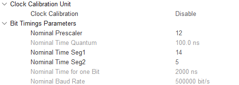
3. Frequency calibration – Disable
4. Bit timing parameters – here you can set the speed of FDCAN
Nominal Prescaler – input frequency prescaler.
Nominal time quantum – duration of one quantum.
Nominal Time Seg1(2) – number of time slices in bit segment 1(2).
Nominal Time for one Bit – the time required to transmit one bit.
Nominal Baud Rate – final data rate for FDCAN.
To correctly configure this block, use the online calculator:
http://bittiming.can-wiki.info/
We select ST Microelectronics bxCAN, in the Clock Rate we indicate the FDCAN input frequency, Sample Point is the point at which the bit is “captured” (for me it is 75%, 87.5 is often used), SJW is “Nominal Sync Jump Width”, this value is from 1 up to 4 by which the duration of Seg1 / 2 segments can be increased or decreased by hardware for better bit capture. The last cell is the rate at which we are setting the FDCAN.

The result will be a table with recommended values (yellow rows are the best settings). From here we take “Prescaler” -> “Nominal Prescaler”,
“Seg1” -> “Nominal Time Seg1”, “Seg2” -> “Nominal Time Seg2”.

5. Turn on the interrupt
In my interrupts, the received data is read.

These are all the FDCAN settings I made in CubeMx.
This article was originally written for an internal forum at the enterprise, but I thought that such information might be useful to others. I honestly admit that the article contains direct copies from other articles (I don’t remember where exactly), but I’ll leave the links where I got the information exactly from, I hope their authors will not be offended by me:
https://www.compel.ru/lib/142251
https://istarik.ru/blog/stm32/159.html
And in general, this is my first article (tutorial), I’m sure that I made mistakes somewhere, so correct it in the comments.