CISCO – Mikrotik – FLEXVPN
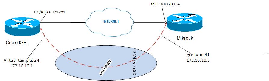
This documentation examines an example of a working configuration for connecting a CISCO router with a Mikrotik router through a GRE tunnel with IPSec encryption in transport mode. The IPsec build will use IKEv2 and certificate authentication issued by ISE-B2B. Inside the tunnel, the OSPF dynamic routing protocol will be raised to exchange routes about networks that are behind peers.
Equipment and initial data:
-
Mikrotik hEX, RouterOS – 7.1beta5
-
Cisco ISR 4331 – IOS 16.9.6
We assume that there is already L3 connectivity between the routers.
Network diagram
Mikrotik configuration
Although mikrotik has its own CLI, we will be configuring through the GUI using “Winbox”. The mikrotik CLI config will be attached to the documentation.
1. Creating a GRE tunnel
Open Winbox-> interfaces -> GRE tunnel -> new

Be sure to specify the name and tunnel destination (Remote Address) of the GRE tunnel. Since it is assumed that the IP address to the external Mikrotik interface will be obtained via DHCP, in the Local Address field, we either do not specify anything or enter “0.0.0.0”
2. Assigning an IP address to the GRE tunnel.
IP -> Address -> new
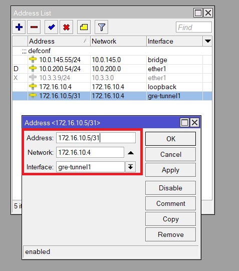
In this menu, enter the IP address of the GRE tunnel with a mask of at least 31 (this is necessary for the further correct operation of OSPF) and select the GRE interface by name, to which we want to assign the IP address (the name is set in item 1)
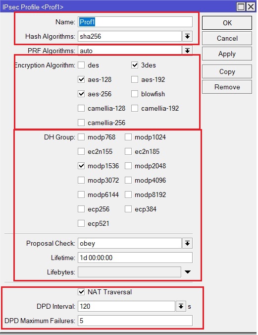
3. Let’s go directly to configuring IPsec itself. The first step is to create an IKEv2 profile. Go to IP -> IPsec -> Profiles -> new. Here we indicate the name of the profile, hashing and encryption algorithms, DH Group, Lifitime IKEv2 SA, DPD operation parameters.
4. Create a new IPsec Peer. Go to IP -> IPsec -> Peer -> new. We give a name to the peer, specify its IP address, do not specify anything in the Local Address field, or specify “0.0.0.0”, as in the GRE interface setting, since the IP address for our Mikrotik is issued via DHCP. We select the profile created in the previous paragraph and the IKE version.

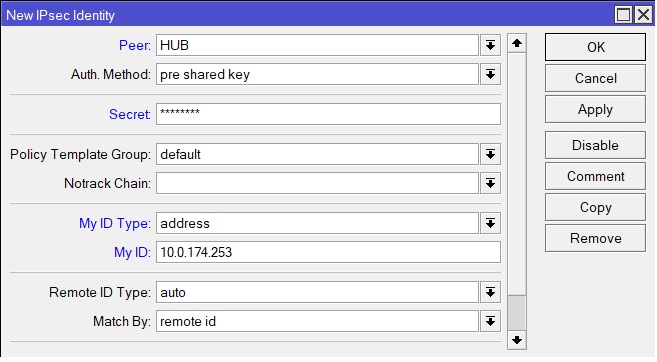
5. It is necessary to configure authentication by certificates between peers. Go to IP -> IPsec -> Identities -> new. Here we select the peer created in the previous paragraph, select Auth. Method – pre-shared key and enter PSK in the Secret field. All other settings can be seen in the picture below.
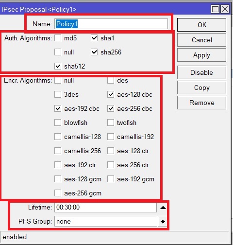
6. Create IPsec Proposal, give it a name, specify encryption and hashing algorithms, IPsec SA lifetime. The PFS Group is not used in our case.
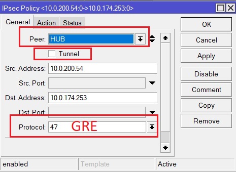
7. Now it remains in the IPsec settings to create an encryption policy, in which we first specify which traffic to encrypt, in our case it is GRE. Go to IP -> IPsec -> Policies -> new -> General. Here we select again the Peer created in step 6, pay attention to the fact that the checkbox next to Tunnel is not checked, since we need to use Transport mode. If Transport mode is used, then Src and Dst Address do not need to be specified, they will be substituted automatically when you click the Apply button. If we want to make changes to the Src and Dst addresses, then this must be done in the Peer settings (point 6). Since we need to encrypt GRE traffic between peers, in the “Protocol” field we indicate 47 – this is the number of the GRE protocol
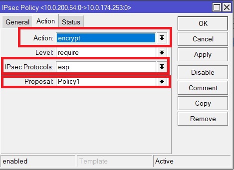
Next, go to the Action tab. Here we check that the “Action” field is “encrypt”, in the “IPsec Protocols” we select “esp” and the “Proposal” field we select the Proposal created in point 6.
To see the status of the tunnel on Mikrotik, you need to go to IP -> IPsec -> Active Peers. If the tunnel goes up successfully, then the Tunnel State should be “Established” and the Tx / Rx packets should be increasing.
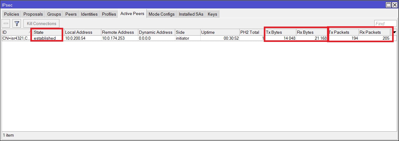
But the counters will begin to grow after traffic flows inside the tunnel, and this will not happen until the dynamic routing protocols in our case, OSPF, are raised on both sides. OSPF settings are described in the following paragraphs.
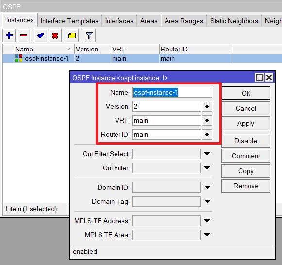
8. Configuring OSPF begins by creating a new OSPF-Instance. Routing -> OSPF -> Instances -> new. Enter the name Instance, and specify everything else as in the picture below.
9. Create OSPF Area. Routing -> OSPF -> Areas -> new. We give it a name, associate it with our OSPF Instance, created in step 10, in our case we use the backbone area, so its Area ID is 0.0.0.0.

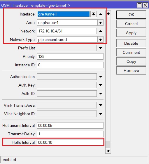
10. It is necessary to enable OSPF on interfaces, first of all on GRE. Routing -> OSPF -> Interface Templates -> new. We select the interface on which we enable OSPF, Area, created in point 11, select the network that is configured on the GRE interface. In point # 2, it was described that the network must necessarily be with a mask of at least 31, if the mask is 32, then OSPF’s neighborhood with cisco will not rise. In “Network type” we select “ptp unnumbered”, since on cisco the tunnel lands on the virtual-template. Checking OSPF Hello Interval.
If everything is configured on the opposite side, then the OSPF neighborhood should rise, and the Tx / Rx packets counters should start to grow (point # 9). You can check the ospf neighborhood in Routing -> OSPF -> Neighbors, State must be “Full”.

Routes received via OSPF can be viewed in IP -> Routes. Routes arriving via OSPF have the Dao flag. The “Gateway” column indicates the interface through which traffic will go towards the network.

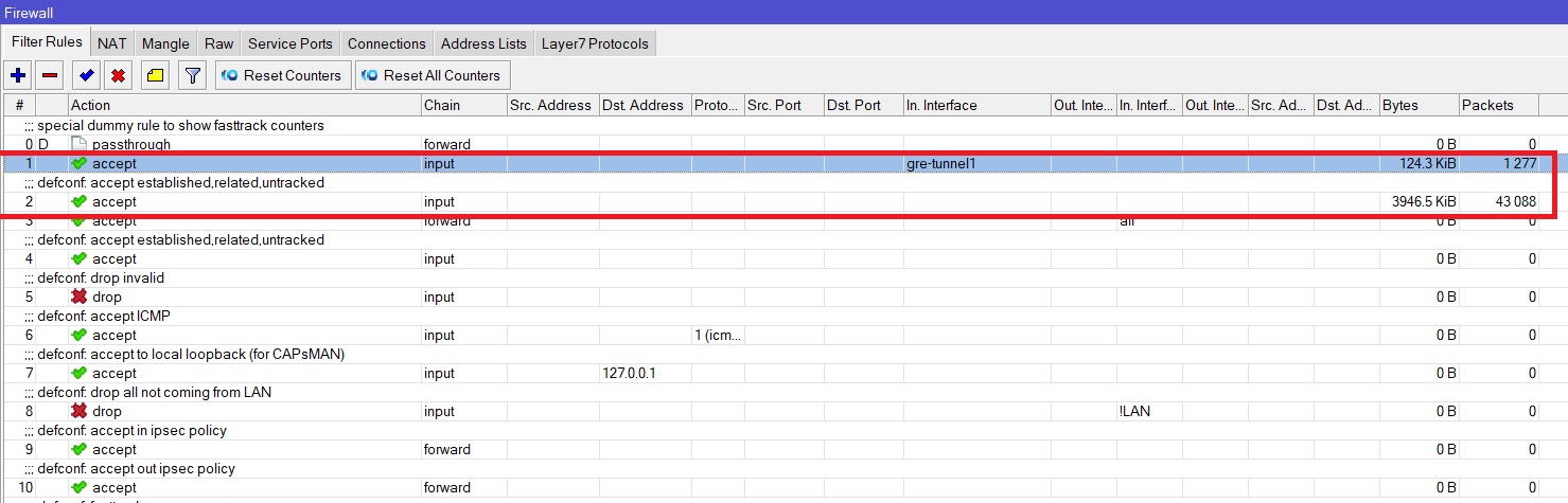
This completes the Mikrotik configuration, you also need to check the Firewall so that legitimate traffic is not blocked.
In this example, all traffic is allowed. Configured here IP -> Firewall -> Filter rules.
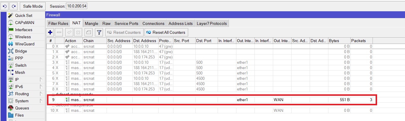
And configured with dynamic Pat. Configured here IP -> Firewall -> NAT.
CISCO configuration
We will configure the Cisco ISR 4331 router through the CLI.
1. We need to make sure that there is no line in the config crypto ikev2 fragmentation mtu <>
If this line is present, it must be removed. Cisco in the 4th IKEv2 build package sends this parameter as a payload, but Mikrotik does not understand it and does not raise the tunnel.
2. Create an ikev2 proposal, give it the name PROP-1, specify the encryption and hashing algorithms, and diffie hellman group.
crypto ikev2 proposal PROP-1

 encryption aes-cbc-256 //алгоритм шифрования aes-cbc-256

 integrity sha256 //алгоритм хэширования sha256

 group 5 //diffie hellman group - 5
Link the Ikev2 proposal to the ikev2 policy.
crypto ikev2 policy IKEV2_POLICY

 proposal PROP-1
3. Create a KEYRING, in which we write PSK, for remote peers
crypto ikev2 keyring KEYRING

 peer ALL

  address 0.0.0.0 0.0.0.0 //данный Keyring подходит для всех пиров

  pre-shared-key local cisco123

  pre-shared-key remote cisco123
4. Create an ikev2 profile.
 crypto ikev2 profile VTI_PROFILE_MIKR

 authentication remote pre-share //используем аутентификацию по PSK для удалённого пира

 authentication local pre-share //используем аутентификацию по PSK для локального пира

 keyring local KEYRING// привязываем KEYRING, в котором находится PSK ключи.

 dpd 10 3 periodic // настраиваем DPD

 virtual-template 2 mode auto // Связываем profile с virtual-template
5. Create ipsec transform-set. We give it a name (TSET), specify the encryption and hashing algorithms and set the transport mode.
crypto ipsec transform-set TSET esp-aes 256 esp-sha512-hmac

 mode transport
6. Create an ipsec profile, name it “IPSEC_PROFILE_MIKR” and link it to the transform-set created in step # 5 and to the ikev2 profile created in step # 4.
crypto ipsec profile IPSEC_PROFILE_MIKR

 set transform-set TSET

 set ikev2-profile VTI_PROFILE_MIKR
7. Create a loopback interface and give it an IP address, this IP address will be assigned to the virtual-template interface. The IP address must be necessarily with a 32 mask – this is necessary for the correct operation of ospf.
interface Loopback1

 ip address 172.16.10.1 255.255.255.255
8. Create virtual-template, give it a number.
interface Virtual-Template2 type tunnel

 ip unnumbered Loopback1 // IP адрес будет браться с loopback1 интерфейса

 ip ospf dead-interval 40 // обозначаем ospf dead интервал.

 ip ospf mtu-ignore // ospf игнорирует значение mtu

 tunnel source GigabitEthernet0/0 // указываем физический интерфейс, с которого будет строиться туннель.

 tunnel protection ipsec profile IPSEC_PROFILE_MIKR // указываем ipsec profile
9. Raise ospf
router ospf 1

network 172.16.10.1 0.0.0.0 area 0 // включаем ospf на интерфейсе Virtual-Template2.
10. Verification
To check whether the tunnel has risen or not, you need to enter the command:
show crypto ipsec sa peer <ip address remote peer>interface: Virtual-Access1
Crypto map tag: Virtual-Access1-head-0, local addr 10.0.174.253
protected vrf: (none)
local ident (addr/mask/prot/port): (10.0.174.253/255.255.255.255/47/0)
remote ident (addr/mask/prot/port): (10.0.200.54/255.255.255.255/47/0)
current_peer 10.0.200.54 port 4500
PERMIT, flags={origin_is_acl,}
#pkts encaps: 68, #pkts encrypt: 68, #pkts digest: 68 // данный счётчики должны расти
#pkts decaps: 66, #pkts decrypt: 66, #pkts verify: 66 // данный счётчики должны расти
#pkts compressed: 0, #pkts decompressed: 0
#pkts not compressed: 0, #pkts compr. failed: 0
#pkts not decompressed: 0, #pkts decompress failed: 0
#send errors 0, #recv errors 0
local crypto endpt.: 10.0.174.253, remote crypto endpt.: 10.0.200.54
plaintext mtu 1442, path mtu 1500, ip mtu 1500, ip mtu idb GigabitEthernet0/0/0
current outbound spi: 0x3F86120(66609440)
PFS (Y/N): N, DH group: none
inbound esp sas:
spi: 0xBD3CDFCA(3174883274)
transform: esp-256-aes esp-sha512-hmac ,
in use settings ={Transport, }
conn id: 2499, flow_id: ESG:499, sibling_flags FFFFFFFF80000008, crypto map: Virtual-Access1-head-0
sa timing: remaining key lifetime (k/sec): (4607991/2947)
IV size: 16 bytes
replay detection support: Y
Status: ACTIVE(ACTIVE)
inbound ah sas:
inbound pcp sas:
outbound esp sas:
spi: 0x3F86120(66609440)
transform: esp-256-aes esp-sha512-hmac ,
in use settings ={Transport, }
conn id: 2500, flow_id: ESG:500, sibling_flags FFFFFFFF80000008, crypto map: Virtual-Access1-head-0
sa timing: remaining key lifetime (k/sec): (4607993/2947)
IV size: 16 bytes
replay detection support: Y
Status: ACTIVE(ACTIVE)
outbound ah sas:
outbound pcp sas:You can check the ospf neighborhood with the command show ip ospf neighbor
Example
show ip ospf neighborNeighbor ID Pri State Dead Time Address Interface
172.16.10.4 0 FULL/ - 00:00:32 172.16.10.5 Virtual-Access1State should be “FULL”, and in the “interface” field we have the value “Virtual-Access1”. This means that the neighborhood is established through the Virtual-Access1 interface.
With this command, we look at the routes received via ospf.
show ip route ospfCodes: L - local, C - connected, S - static, R - RIP, M - mobile, B - BGP
D - EIGRP, EX - EIGRP external, O - OSPF, IA - OSPF inter area
N1 - OSPF NSSA external type 1, N2 - OSPF NSSA external type 2
E1 - OSPF external type 1, E2 - OSPF external type 2
i - IS-IS, su - IS-IS summary, L1 - IS-IS level-1, L2 - IS-IS level-2
ia - IS-IS inter area, * - candidate default, U - per-user static route
o - ODR, P - periodic downloaded static route, H - NHRP, l - LISP
a - application route
+ - replicated route, % - next hop override, p - overrides from PfR
Gateway of last resort is 10.0.131.1 to network 0.0.0.0
10.0.0.0/8 is variably subnetted, 10 subnets, 3 masks
O 10.0.145.0/24 [110/1001] via 172.16.10.5, 11:11:06, Virtual-Access1In the example above, traffic to the destination network 10.0.145.0/24 will go through the Virtual-Access1 interface.