Benchtop flywheel balancing
It was in the evening, there was nothing to do (c)
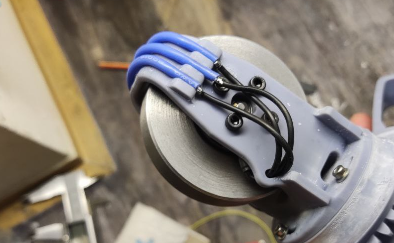
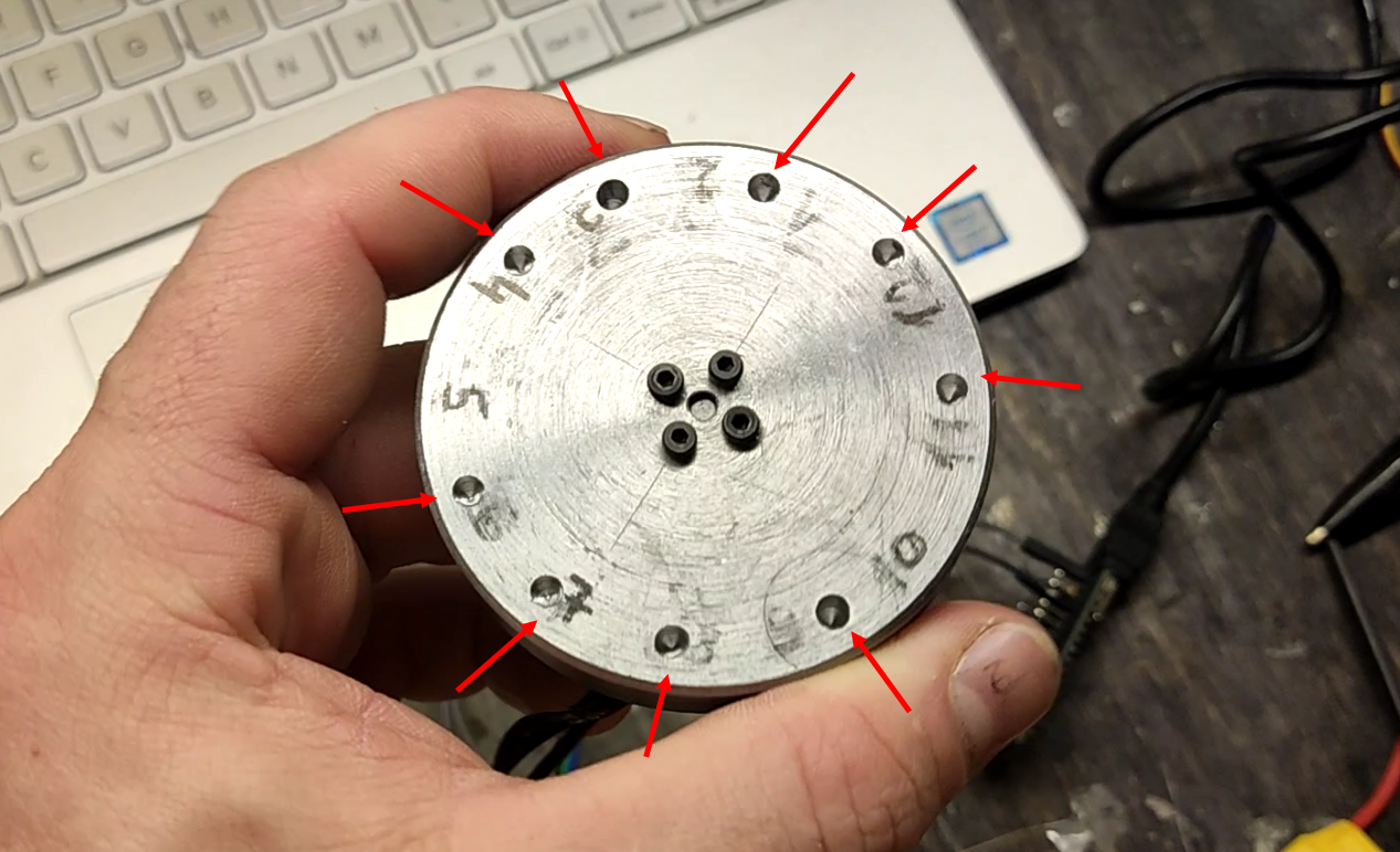
Somehow surfing the net, I came across one project, which even had a patent. The project is related to power gyroscopes and a stabilization system, but now we are not talking about that a bit. To implement this product, as you understand, gyroscopes are needed. I tried to find a ready-made solution, because I understood that the biggest difficulty in manufacturing is balancing the gyroscope flywheel. And, of course, I didn’t find it. As a motor, I used a brushless motor, like this, but what can we say, it was he who chose him for his experiments. The choice fell on him, for the reason that the flywheel is fastened not with one central screw, but with four small screws located around the circumference.
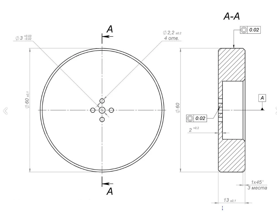
Well, you need a flywheel. I quickly drew a drawing, sent it to the turner, waited a bit and got the finished product.
I screwed one from the other and got such a simple design.

It remains to be screwed to the base so that this thing does not roll around the table cheerfully and serenely.
When launched, this whole unknown structure vibrates violently, and look – it will fall apart now. It made me feel scared and somehow uncomfortable. There was a decision to assemble a homemade stand for balancing. Because I have very little experience in developing electronics and firmware for controllers; In fact, no, then I had to collect information from various sources.
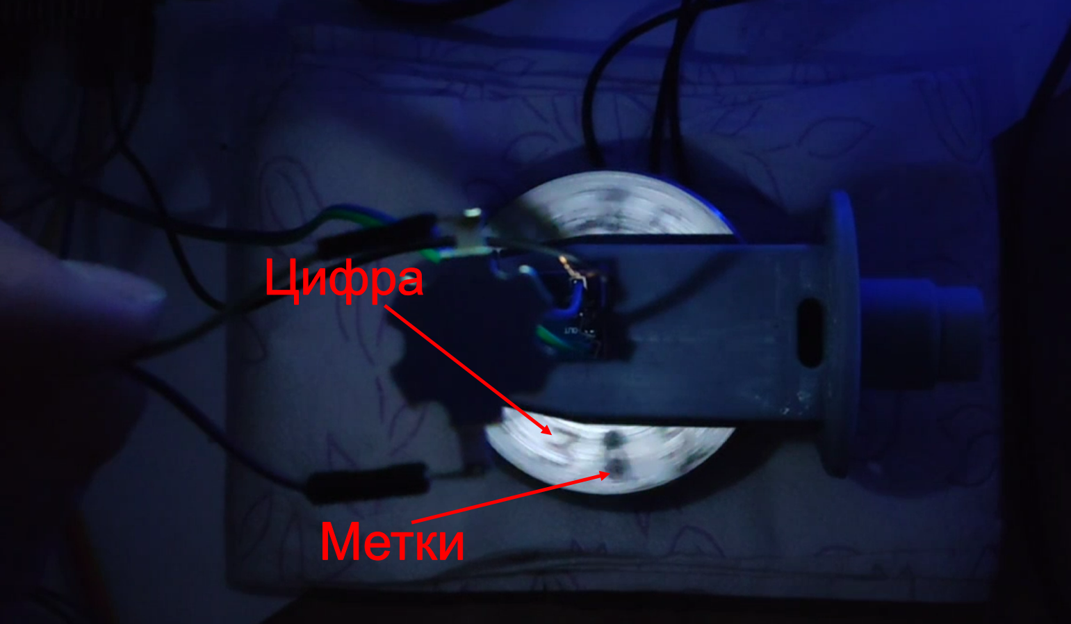
I roughly understood how a balancing machine works – we are looking for a vibration peak, we remember or somehow indicate the place where this peak was found. Everything is simple. In my case, I will use an LED to illuminate the “heavy” part of the flywheel.
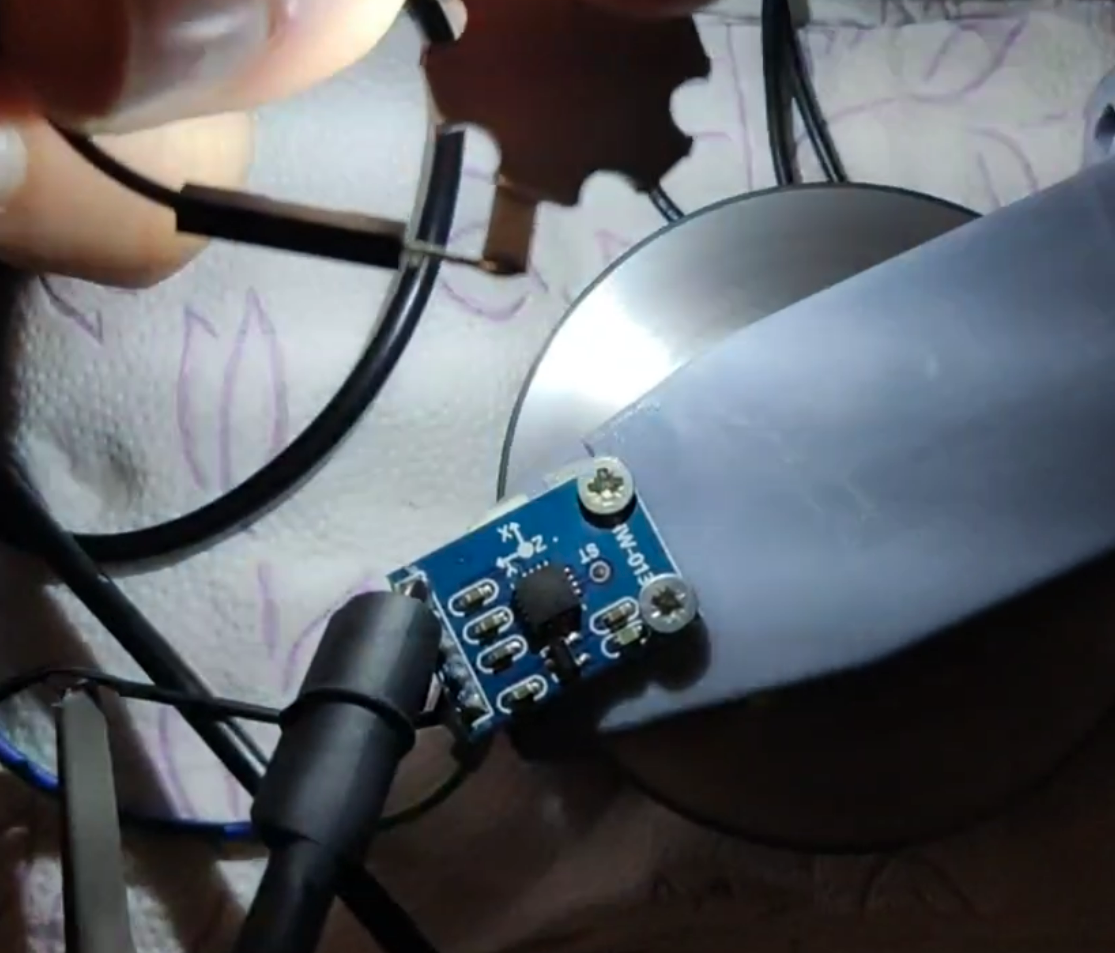
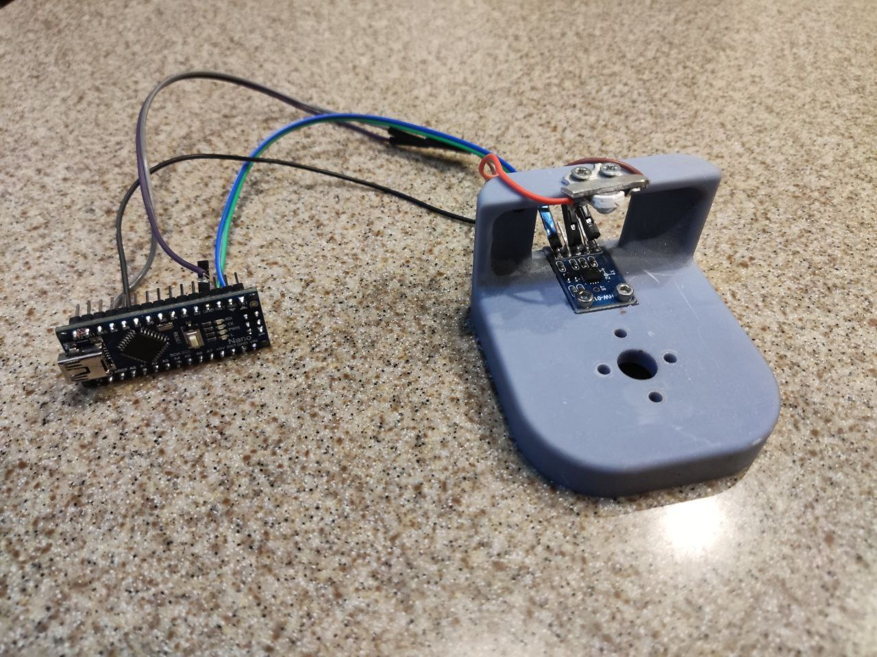
As a sensor, I decided to use an accelerometer. I read these your Internets and realized that you need to use an analog accelerometer, for example ADXL-335. This is due to the fact that digital outputs have filters, but I need raw data and I want to process it myself. Perhaps it is not. If not, correct it. By the way, the frequency is more than 400 Hz with this accelerometer cannot be measured.
Decided to use it as an LED. 1W LED. I put it through a current-limiting resistor of 27 Ohm, with the hope that the arduino (LED) will pull it through the load. In principle, she pulled out, there were no interruptions.
As a controller, I took a scarf with Arduino Nano. It’s inexpensive and pretty small.
First, I hung everything on the snot on the existing bracket to test the performance of the whole idea. It looked pretty sad.

I collected everything, I decided to see what was there at the output from the accelerometer. But what is there, such a sinusoid.
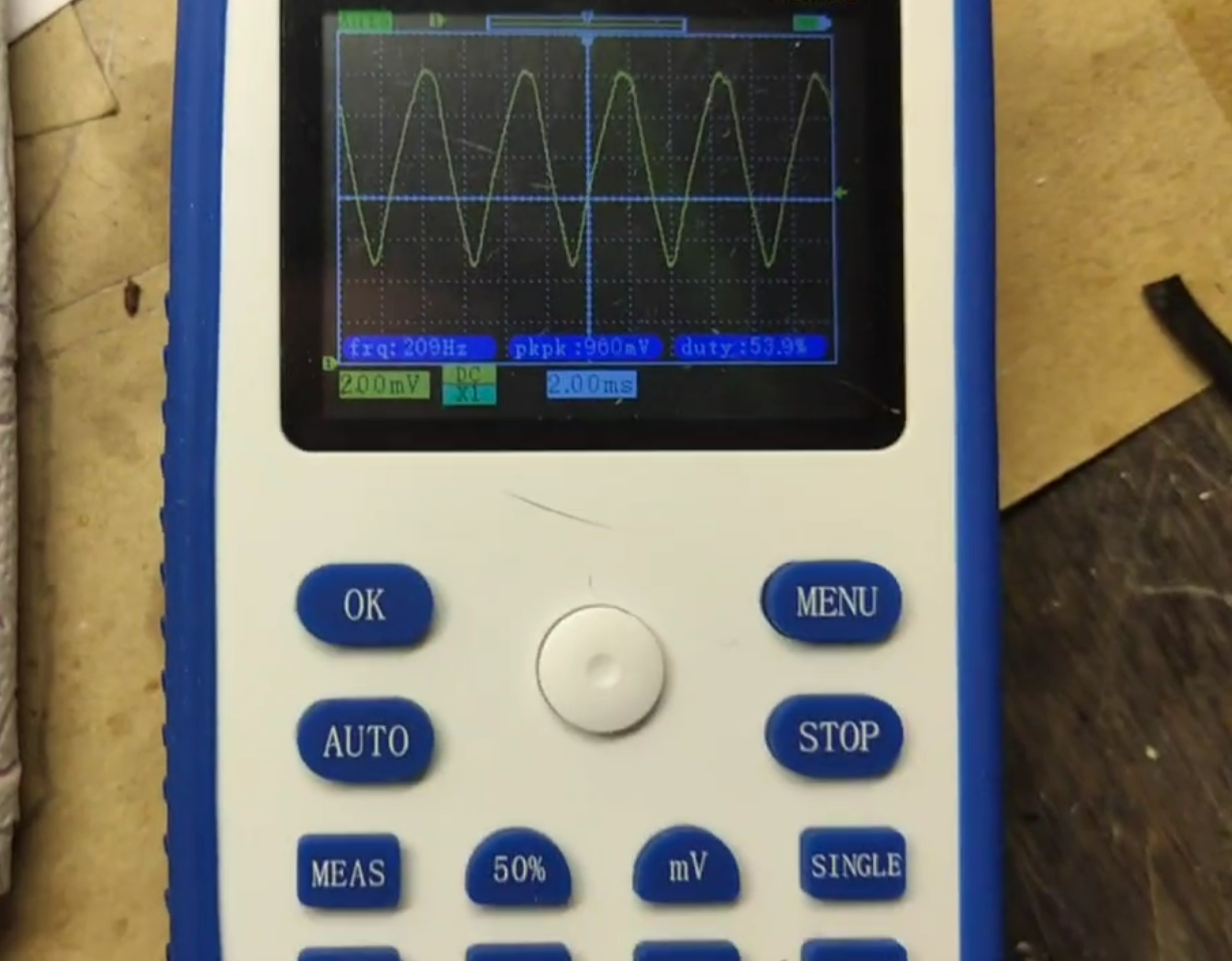
What I thought and how I imagined. While I am at the top of the sinusoid, I will turn on the LED. It seemed to me extremely logical and quite workable. Added a potentiometer to adjust the “height” of the threshold
I wrote this short program.
First firmware
int axel = A0;    // аналоговый акселерометр
int reg = A1;    // потенциометр
int ledPin = 13;      // светодиод
void setup() { pinMode(ledPin, OUTPUT);} //мегакоТ
void loop() {
if (analogRead(axel)>analogRead(reg))  digitalWrite(ledPin, HIGH); //чтение. сравнение и включение светодиода
else digitalWrite(ledPin, LOW);// выключение светодиода
}
With anticipation, I poured it into the microcontroller and nothing happened. Sometimes, you could see the marks on the flywheel, but these were accidents.
After consulting with smart people, I realized that it is necessary to detect the peak more accurately and unambiguously, this is the first, second – the length of the LED pulse must be set independently, and not as I had (the length of the backlight depends on the rotational speed and response threshold). And you can also use special magic to increase the speed of the ADC.
Based on these changes, firmware 2 was born. I didn’t invent anything, I took ready formulas.
Second firmware
int axel =  A0   ;  // аналоговый акселерометр
int ledPin   =13 ;    // светодиод
int minADC = 1023; // присваиваю начальное значение переменной
int maxADC = 0; // присваиваю начальное значение переменной
int nowADC = 0; // присваиваю начальное значение переменной
bool maxIsWorked = true; // присваиваю начальное значение переменной
bool minIsWorked = true; // присваиваю начальное значение переменной
uint32_t timer; // присваиваю тип переменой (целые числа)
float freq, ampV, A, S, V, m; // присваиваю тип переменой (числа с плавающей запятой)
void setup() {
pinMode(ledPin, OUTPUT);  // ledpin будет выход
Serial.begin(2000000); // настройка скорости com порта
ADCSRA |= (1 << ADPS2); // магия 1
ADCSRA &= ~ ((1 << ADPS1) | (1 << ADPS0)); // магия 2
}
void loop() {
nowADC = 1023-analogRead(axel); //реверс сигнала, изменения направления оси
if (nowADC > maxADC) {
maxADC = nowADC;
}
else if (nowADC < minADC) {
minADC = nowADC;
}
else if (maxADC > nowADC + 10 and minIsWorked) {
maxIsWorked = true;
minIsWorked = false;
//кусок выше - условия, при которых ищу пик на синусоиде
uint32_t nowTime = micros(); //записываю текущее время в мкс в переменную nowTime
Serial.println("xx");
freq=1000000 / (nowTime - timer); //вычисляю частоту сигнала с акселерометра, Гц
ampV=(maxADC-minADC)4.87;//вычисляю амплитуду сигнала, мВ A=ampV/3009.8;//вычисляю виброускорение в м/с^2
S=A25.35/freq/freq;//вычисляю виброперемещение, мм V=S0.63freq;//вычисляю виброскорость, мм/с m=8040.3V/(2.5freq*60); // вычисляю массу на радиусе 2 см, при массе всего ротора 300 г, пытался вычислить массу, которую необходимо убрать с маховика. не вышло
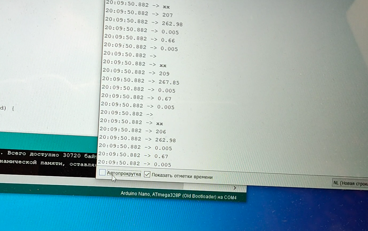
Serial.println(freq, 0);
Serial.println(ampV);
Serial.println(S, 3);
Serial.println(V);
Serial.println(m, 3);
Serial.println(" ");
timer = nowTime;
digitalWrite(ledPin, HIGH);
delayMicroseconds(12); //время свечения светодиода в мкс
digitalWrite(ledPin, LOW);
minADC = 1023;
//кусок выше - вывод данных в порт
}
else if (minADC < nowADC - 10 and maxIsWorked) {
maxADC = 0;
maxIsWorked = false;
minIsWorked = true;
}
}
And only after that happened what happened!
Because it is necessary to balance not one product, but several, then I sawed down a desktop microstand. painted designed, printed and assembled.
I put the motor with a flywheel on the stand, marked the flywheel, spun it, measured the vibration velocity (it was by this parameter that I decided to evaluate the vibration). Found a place to lighten the flywheel.
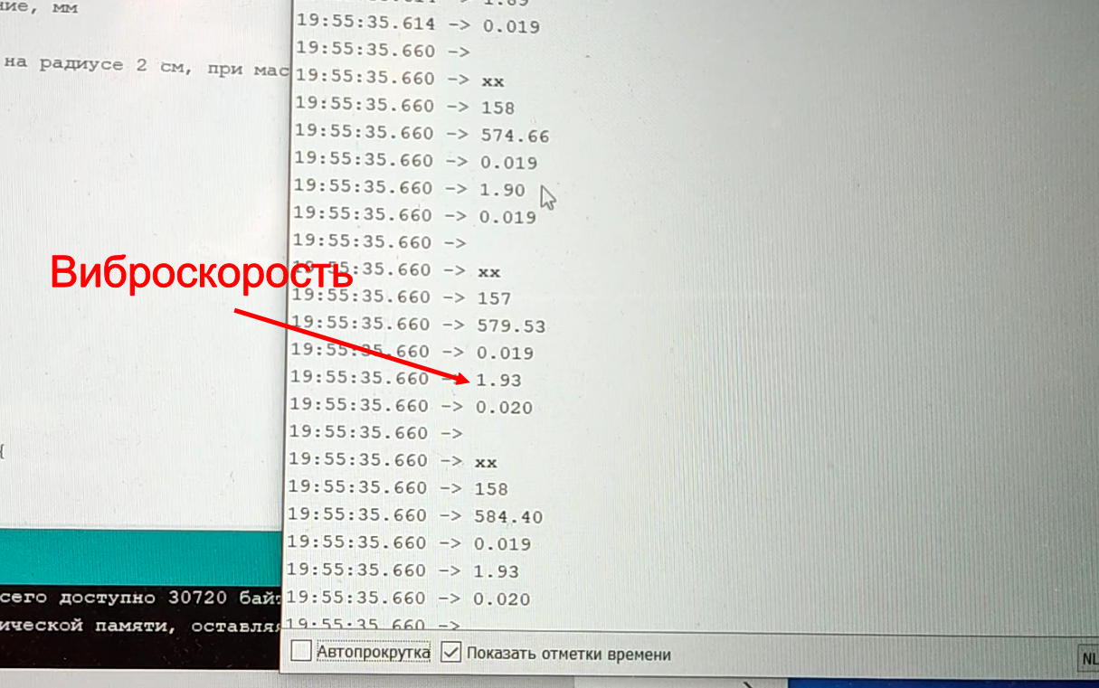
The vibration velocity before balancing was 1.9 mm/s.
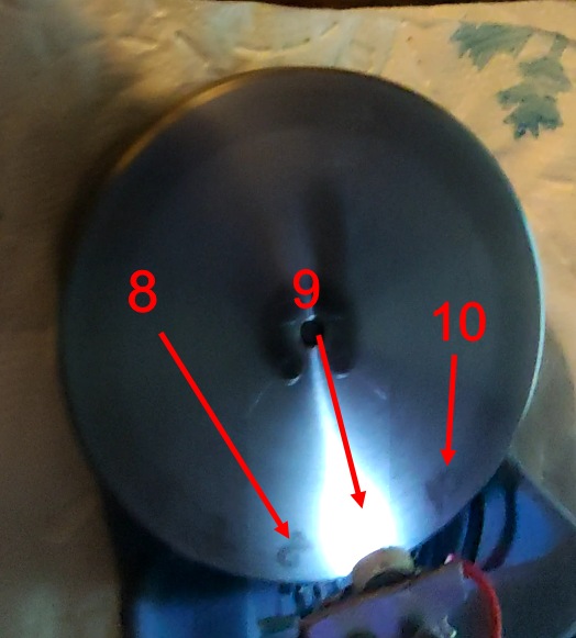
The found place from which it is necessary to remove the material (about nine).
The process of removing excess mass. The magnet is needed so that the chips do not scatter in different directions and do not get into the motor, for example.
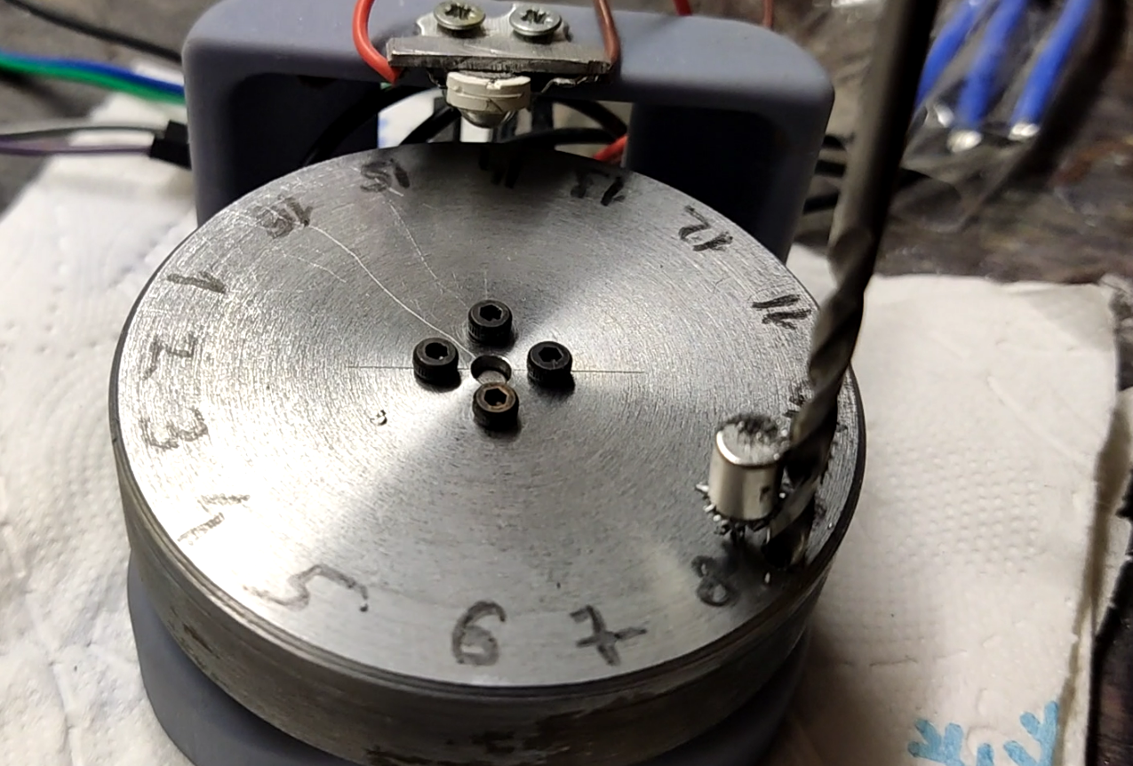
After drilling, I start the flywheel and look at how much the picture has changed. I drill either a hole further in depth, or I drill a hole in another place.
As a result, the vibration velocity dropped to 0.6 mm/s.
Can you tell me if it can be further reduced? In this work, I was unable to do so. Apparently, the quality of bearings, backlash, retrograde Mercury or other influences are already beginning to affect. And I tried, I tried. The result is cheese.
But this result is more than enough for me. Of course, there is vibration, you can feel it with your fingernail, but the body, with the installed motor and flywheel, no longer jumps on the table and does not destroy itself.
In general, it was possible to study the vibration velocity at different frequencies, to be puzzled by measuring the vibration velocity in two supports, as adult uncles do on large machines, in order to carry out more accurate balancing, but I achieved what I needed in the first approximation and stopped there.
Below is a slightly different presentation of information, but there are bare legs and winter.