Arduino Tracked Robot Chassis, Part 1
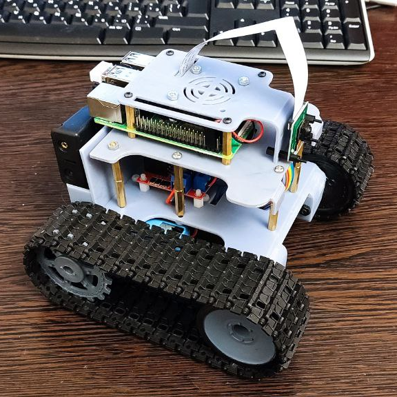
It was evening, there was nothing to do. I somehow caught fire with the creation of a universal caterpillar platform for studying Tensorflow. Moreover, I wanted to make control through the ESP32, which will regulate the motors, if desired, will give control through a browser on the local network, and the Raspberry Pi will control it, imitating myself. Plus the ability to permanently solder the ESP32 and update it over the air. Here I want to outline the approximate chronology of creation.
Full list of spare parts:
Raspberry Pi 4b – 1 PC. // for machine vision.
Camera for Raspberry Pi – 1 PC.
ESP32 – 1 PC. // MK for controlling motors and in the future for reading readings from motion sensors.
TT motor with a metal gear – 2 pcs.
L298N – 1 PC. //motor driver – you can, you even need to use something more compact and fresh, but I had it lying around idle.
Tracked tracks – 2 pcs.
Batteries type 18650 – 2 pcs.
Battery box – 1 PC.
wires
Screws, nuts and standoffs M2, M2.5 and M3.
No sooner said than done, such caterpillar tracks were obtained from Aliexpres, a printed bushing is included under the TT motor, which does not fit at all – but this is not a problem, there is a 3D printer.

Why were caterpillar tracks chosen? I would like to say that I dreamed of high cross-country ability, grip indicators, but I will not lie, the model is small in size and I just wanted it on tracks.
Having decided on all the components, I began to design in Fusion 360. The main goal was minimalism, I wanted a small craft with a clearly planned workspace, which I think I was able to achieve, but it’s not for me to judge.
Separately, I would like to draw your attention to some details of the frame:
This is what the frame looks like:


I had to strengthen the frame (highlighted in red), otherwise, under the tension of the tracks, the frame bent. Naturally, the material from which I printed this model is to blame for everything – the usual photopolymer resin from Anycubic.

: Also in the model itself, I provided for a quick removal / installation of tracks with tension, but it looks nowhere easier:

A support shaft is inserted into the lower left side and guided along the groove and a screw is inserted, which is fixed on the reverse side with a nut.
Well, the rest is ordinary – just connectors for everything in the world:
A button, TYPE-C connectors, channels for wires, for every platform for the SG90 servo (a tribute to Chinese cars with HC-SR04).
Accordingly, all the details for printing look like this:

Printed everything on Anycubic M3. Having printed the first model, I immediately decided to implement manual control through the phone. Since I am far from a programmer, I decided to use a ready-made library, the choice fell on GyverPortal. Everything looks like this:

Yes, it’s clumsy, but it works, and this is the most important thing, then you can finish / redo everything, now the goal is to come to a working prototype. The code is also clearly far from ideal, but it works.
Remote control code:
remote control code
#define AP_SSID ""
#define AP_PASS ""
#include <GyverPortal.h>
GyverPortal ui;

// Motor A
int motor1Pin1 = 27;
int motor1Pin2 = 26;
int enable1Pin = 14;
// Motor B
int motor2Pin1 = 25;
int motor2Pin2 = 33;
int enable2Pin = 32;

int valSlider;
int push=0;
int speed=0;
void setup() {
pinMode(motor1Pin1, OUTPUT);
pinMode(motor1Pin2, OUTPUT);
pinMode(enable1Pin, OUTPUT);
pinMode(motor2Pin1, OUTPUT);
pinMode(motor2Pin2, OUTPUT);
pinMode(enable2Pin, OUTPUT);

digitalWrite(motor1Pin1, LOW);
digitalWrite(motor1Pin2, LOW);
digitalWrite(motor2Pin1, LOW);
digitalWrite(motor2Pin2, LOW);

startup();

// подключаем конструктор и запускаем
ui.attachBuild(build);
ui.attach(action);
ui.start();
}

void build() {
GP.BUILD_BEGIN();
//GP.THEME(GP_DARK);
GP.THEME(GP_LIGHT);

GP.TITLE("ESP32 ROBOT");
GP.HR();

M_BLOCK(
GP.LABEL("Статус системы");
GP.BREAK();
GP.LABEL("19%🔋");

);


M_BLOCK_THIN_TAB(
"Ручное Управление",
GP.LABEL("Пульт");
M_BOX(
//GP_CENTER,
GP.BUTTON("btntopleft", " ⬉ ");
GP.BUTTON("btntop", " △ ");
GP.BUTTON("btntopright", " ⬈ ");
);
GP.BREAK();
M_BOX(
//GP_LEFT,
GP.BUTTON("btnleft", " ◁ ");
GP.BUTTON("btnactive", " 🛑 ");
GP.BUTTON("btnright", " ▷ ");
);
GP.BREAK();
M_BOX(
//GP_CENTER,
GP.BUTTON("btnbottomleft", " ⬋ ");
GP.BUTTON("btnbottom", " ▽ ");
GP.BUTTON("btnbottomright", " ⬊ ");
);
M_BOX(GP.LABEL("Скорость"); GP.SLIDER("sld", valSlider, 0, 255); );
);
GP.BUILD_END();
}


void action() {
// обработчик изменения состояния кнопок
if (ui.clickInt("sld", valSlider)) {
Serial.print("Slider: ");
Serial.println(valSlider);
}
}

void loop() {

push=push-1;
speed=valSlider;
if (push<=0){
digitalWrite(motor1Pin1, LOW);
digitalWrite(motor1Pin2, LOW);
digitalWrite(motor2Pin1, LOW);
digitalWrite(motor2Pin2, LOW);
analogWrite(enable1Pin, 0);
analogWrite(enable2Pin, 0);
}


ui.tick();

// проверяем через свой флаг

if (ui.hold("btntopleft")){
  push=4;
digitalWrite(motor2Pin1, LOW);
digitalWrite(motor2Pin2, HIGH);
digitalWrite(motor1Pin1, LOW);
digitalWrite(motor1Pin2, HIGH);
analogWrite(enable1Pin, 255);
analogWrite(enable2Pin, 140);
}
if (ui.hold("btntop")){
  push=4;
digitalWrite(motor2Pin1, LOW);
digitalWrite(motor2Pin2, HIGH);
digitalWrite(motor1Pin1, LOW);
digitalWrite(motor1Pin2, HIGH);
analogWrite(enable1Pin, speed);
analogWrite(enable2Pin, speed);
}
if (ui.hold("btntopright")){
  push=4;
digitalWrite(motor2Pin1, LOW);
digitalWrite(motor2Pin2, HIGH);
digitalWrite(motor1Pin1, LOW);
digitalWrite(motor1Pin2, HIGH);
analogWrite(enable2Pin, 255);
analogWrite(enable1Pin, 140);
}
if (ui.hold("btnleft")){
  push=4;
digitalWrite(motor2Pin1, LOW);
digitalWrite(motor2Pin2, LOW);
digitalWrite(motor1Pin1, LOW);
digitalWrite(motor1Pin2, HIGH);
analogWrite(enable1Pin, speed);
analogWrite(enable2Pin, speed);
}
if (ui.hold("btnactive")){
  push=0;
analogWrite(enable1Pin, 0);
analogWrite(enable2Pin, 0);
}
if (ui.hold("btnright")){
  push=4;
digitalWrite(motor2Pin1, LOW);
digitalWrite(motor2Pin2, HIGH);
digitalWrite(motor1Pin1, LOW);
digitalWrite(motor1Pin2, LOW);
analogWrite(enable1Pin, speed);
analogWrite(enable2Pin, speed);
}
if (ui.hold("btnbottomleft")){
push=4;
digitalWrite(motor2Pin1, HIGH);
digitalWrite(motor2Pin2, LOW);
digitalWrite(motor1Pin1, HIGH);
digitalWrite(motor1Pin2, LOW);
analogWrite(enable1Pin, 255);
analogWrite(enable2Pin, 140);
}
if (ui.hold("btnbottom")){
  push=4;
digitalWrite(motor2Pin1, HIGH);
digitalWrite(motor2Pin2, LOW);
digitalWrite(motor1Pin1, HIGH);
digitalWrite(motor1Pin2, LOW);
analogWrite(enable1Pin, speed);
analogWrite(enable2Pin, speed);
}
if (ui.hold("btnbottomright")){
  push=4;
digitalWrite(motor2Pin1, HIGH);
digitalWrite(motor2Pin2, LOW);
digitalWrite(motor1Pin1, HIGH);
digitalWrite(motor1Pin2, LOW);
analogWrite(enable2Pin, 255);
analogWrite(enable1Pin, 140);
}
}


// пишет в порт по своему таймеру
void asyncPrint(const char* str) {
static uint32_t tmr;
if (millis() - tmr >= 500) {
tmr = millis();
Serial.println(str);
}
}


void startup() {
Serial.begin(115200);
WiFi.mode(WIFI_STA);
WiFi.begin(AP_SSID, AP_PASS);
while (WiFi.status() != WL_CONNECTED) {
delay(500);
Serial.print(".");
}
Serial.println(WiFi.localIP());
}
At the time of the first tests, everything looked something like this:
It moves, so you can go further. Next, a cover-fastener for the Raspberry Pi was designed, on which a 5V cooler and a camera are attached, there is no goal to close it from the whole world, at least for now.
That’s all for the first part for now, in the near future I plan to change the battery box to a Chinese homemade product with built-in charging and a voltage regulator, but about this and about the torment with the Raspberry Pi of the second part, if the first one is of interest to anyone.


If anyone is interested in this project, then I am ready to post the source code of the model with the corresponding further updates. Also open to criticism/questions/suggestions. Thanks for reading!