Accelerate RF, Microwave Design (4/5)

RF, Microwave boards are one of the fastest growing sectors in PCB manufacturing. With the proliferation of IoT sensors, wireless electronics and smartphones, it’s easy to see why. But how do you know if you are working with an RF or microwave board? The PCB industry believes that any board operating above 100 MHz is an RF board. Anything approaching 2 GHz is microwave.
Lesson 4 – Advanced RF Trace Capabilities
In this lesson, we will look at the special features of PADS Professional for tracing RF channels.
- Double click on the PADS Pro Designer VX.2.x icon on the desktop or select
START Menu> PADS Pro Tools VX.2.x> PADS Pro Designer VX.2.x. - From the PADS Professional Designer start page, click Open and open
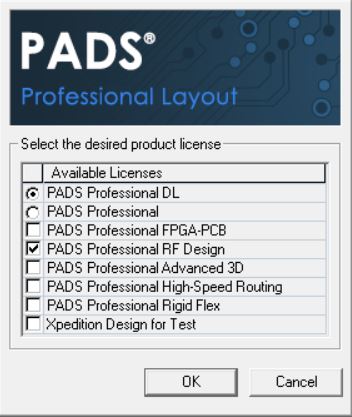
C: RF Design Lesson4 PCB Lesson4.pcb.- If a licensing dialog box appears, make sure the option PADS Professional RF Design installed and click OK
- Make sure display scheme is selected RF Routing… This will make the RF toolbar visible.
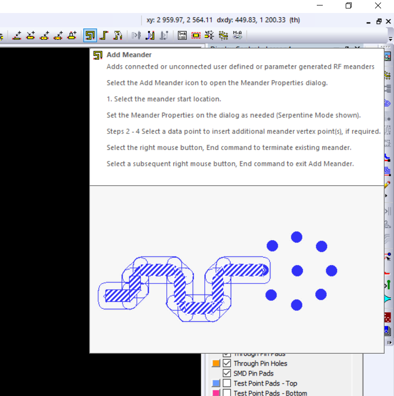
- There are 2 dedicated RF tracing tools available: Add meander and Route Meander… Options Add and Route are very similar in functionality. Add provides more precise control and supports a dedicated conductor tuning option. Route more simple and convenient to use, but in some cases its functionality may not be enough. In this tutorial, we’ll be using both of these tools:
- For antenna trace TX we will use the tool Add meander… Please select Add meander on the RF toolbar
- Click on the pin TX2 amplifier in BGA package as shown in the picture:

- Default Corner Type installed on Miter… Change the value to Free Radius and lay a route from the pin to the antenna. Pay attention to how the route is laid
- Undo the last action. Re-trace, but this time set Corner Type = Miter… Do not forget to set the reference point before connecting to the antenna itself in order to reduce the length of the taper.
- Now let’s lay a route for TX1, at the same time agreeing its length with TX2 with serpentine
- If the function is not active, select again Add meander on the toolbar
- Click on pin TX1 and start routing
- Click to fix the trace (set a control point) opposite the antenna input
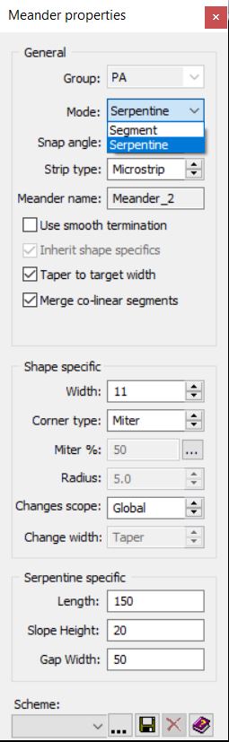
- Return to the dialog while tracing Meander and change General Mode on the Serpentine
- You should see a serpentine (snake) where the track has already been laid. Adjust the serpentine parameters as follows:
- Length: 150
- Slope Height: twenty
- Gap Width: fifty
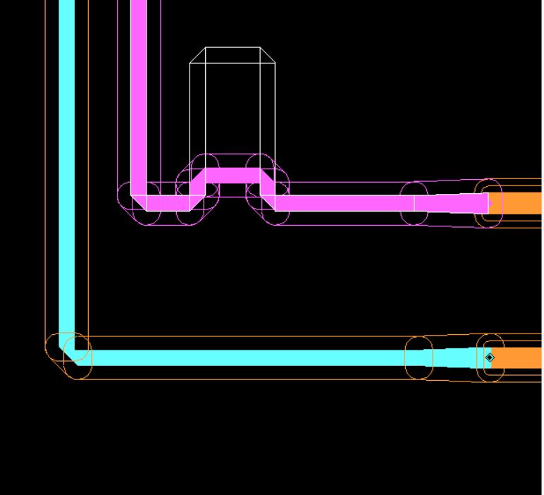
- Connect the track to the antenna. Remember to set the reference point just before connecting to the antenna itself to minimize the effect of the taper
- You should get the following output:

- Let’s do some changes to the track
- Highlight the track TX2
- Click PKM and select RF Parameters
- To adjust the corner taper, click on the field Miter% and set the value 60
- Click Apply

- Now you need to check and correct the added serpentine. Through dialogue RF Parameters you can check the conductor length for TX2 and TX1. To change the length of the serpentine, use the function Edit meander:
- Select the upper segment of the serpentine
- Click PKM and select Edit meander
- Now you can move the upper segment of the serpentine up to increase the length of the wire. Adjust until the length is within 10 mils from TX2
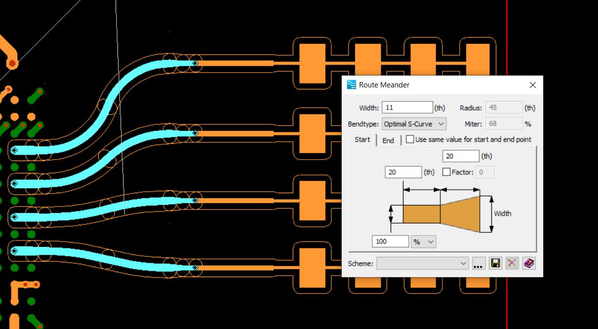
- After we have routed TX signals can now go to RX… To trace these 4 nets, we will use the tool Route Meander:
- Activate the tool Route Meander

- Check out the settings dialog, but don’t make any changes
- Select one of the RX nets and route from the amplifier pin (BGA) to the antenna port
- Repeat this process for all 4 circuits.
- You can also use standard RF tracing capabilities
- Delete one of the paved tracks
- Just click Paintwork along the route indicated in the picture

- Click the button Delete on keyboard
- Click on F3to activate interactive tracing
- Route from amplifier (BGA) to antenna port
- Normal conductor can be converted to RF square wave so you can apply advanced rules or add bevels to corners
- To select the entire conductor, click on the segment shown in the figure
- Click PKM and select Selection> Add Partially Selected Traces
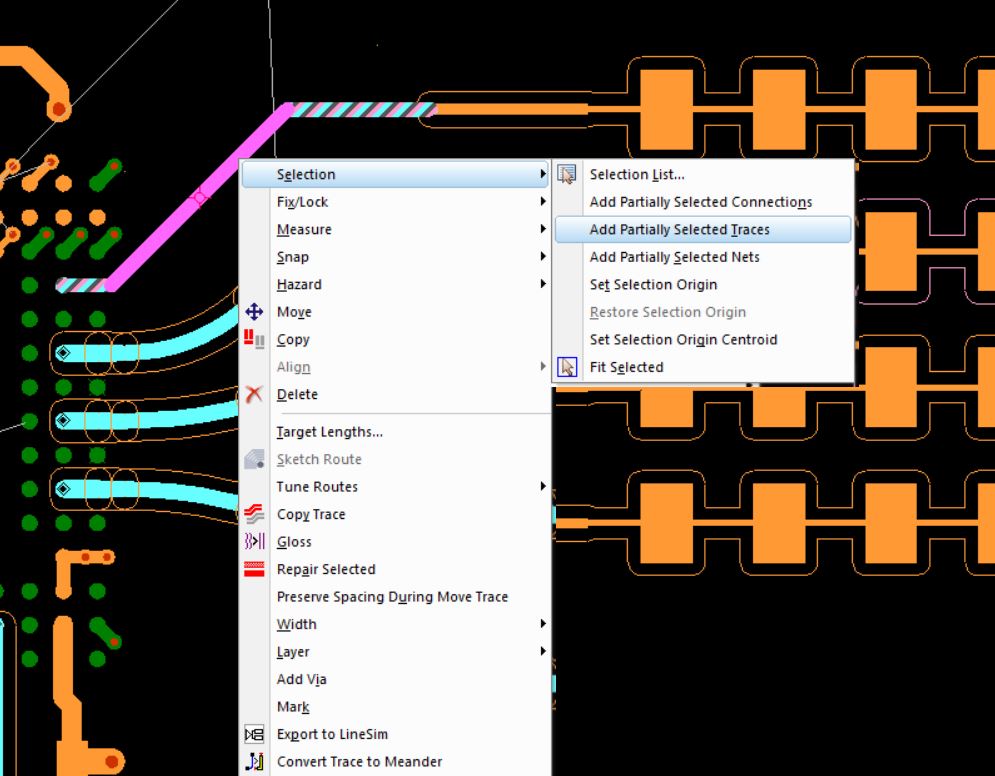
- Click PKM again and select Convert to Meander
- In the dialog box Convert Trace to Meander select a value from the Group list PA
- Click on Convert
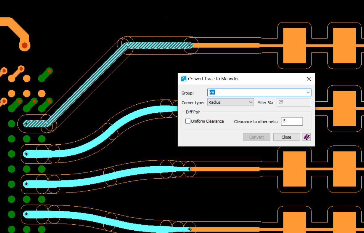
- Rule areas appear around the alignment, similar to the traces you have routed.
- This concludes Lesson 4.
Test 30-day licenses can be requested HERE
Materials for this and subsequent lessons can be downloaded HERE
You can also watch a video version of this tutorial:
Similar Posts
- Just click Paintwork along the route indicated in the picture
- After we have routed TX signals can now go to RX… To trace these 4 nets, we will use the tool Route Meander:
- Now you need to check and correct the added serpentine. Through dialogue RF Parameters you can check the conductor length for TX2 and TX1. To change the length of the serpentine, use the function Edit meander:
- Click on the pin TX2 amplifier in BGA package as shown in the picture:
- If a licensing dialog box appears, make sure the option PADS Professional RF Design installed and click OK