A rocket from Amperka, part 3: Turning machine, stand finished, electronics
In this post I will tell you what we got in the next week of work on the rocket project.

Let me remind you that this series of articles is a blog dedicated to how we build a rocket from scratch, without knowledge and skills. Articles are published weekly on Saturdays.
Those who are with us for the first time, please read the entire history of the project. I ask the regulars under the cat.
Turning turner
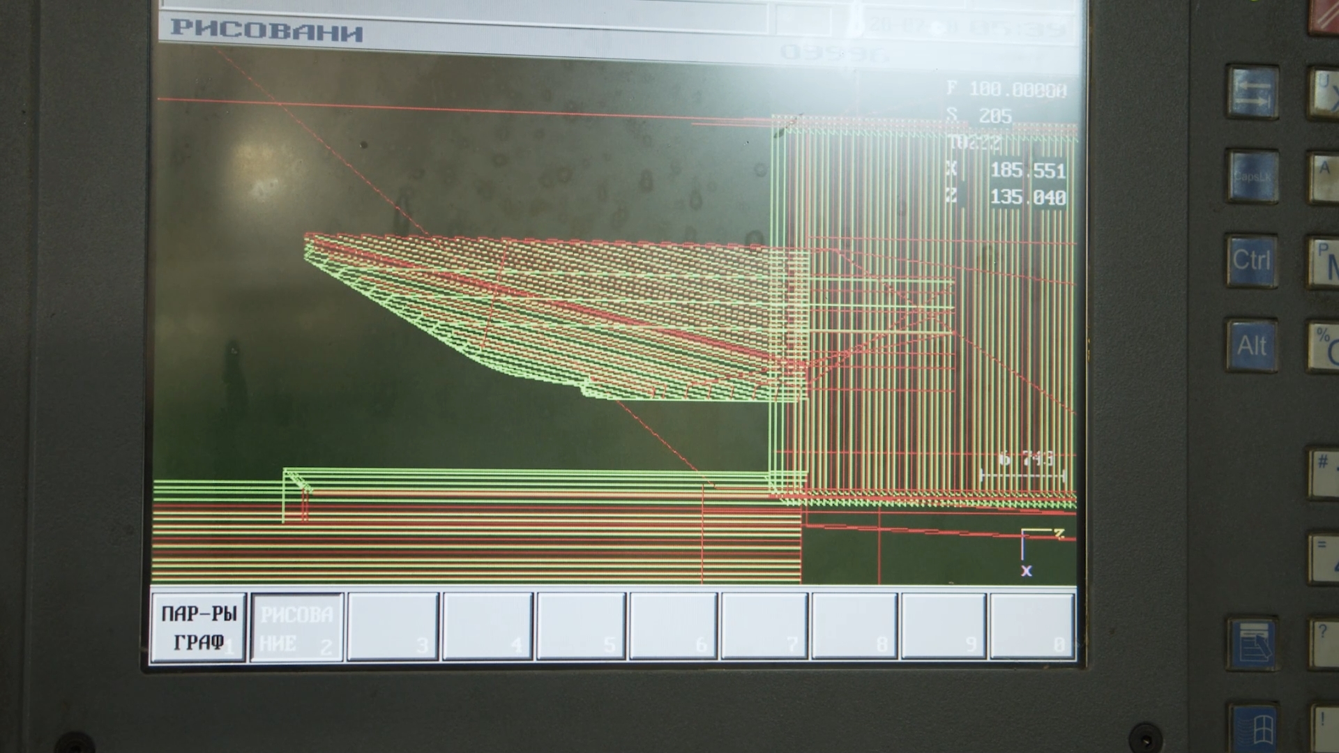
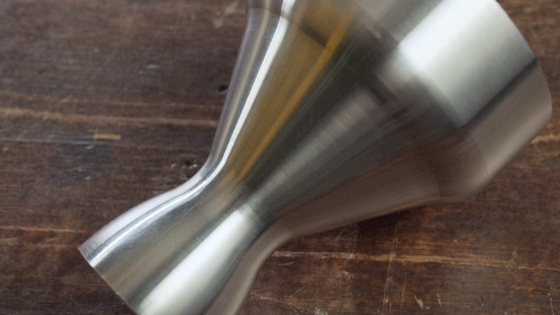
In the previous series, we calculated the nozzle profile based on the data obtained from the Meteor and Rocki-nozzle programs, drew a drawing and began to think about its implementation in metal. Since our nozzle was built on curves, and not just two aligned cones, we wanted to realize this potential in full. When turning by hand, such accuracy could not have been achieved even by a turner with many years of experience, so they began to look in the direction of CNC turners.
We searched the Internet in search of custom-made production – either a minimum batch of a thousand pieces, or piece production at the cost of a Boeing wing. And it’s unlikely that we would have been allowed to shoot the process for a video report. Therefore, without further ado, I typed my friend, he has a good lathe, and perfectionism just rolls over, so there was no need to worry about accuracy. They threw off the model, Kirill (the turner) agreed, and as soon as we were about to advance to him with our friendly company, he got a machine. Painful and sad, I had to endure.
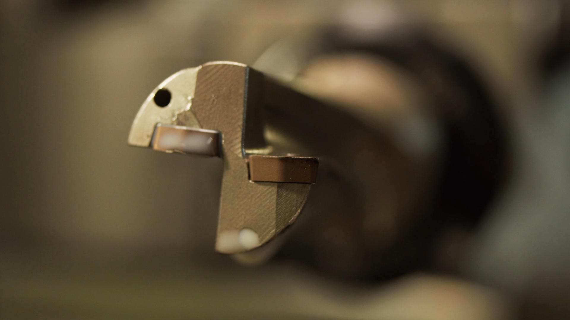
But we waited and arrived. Kirill explained to us that for normal operation under conditions of such temperature and friction of gases, the billet we bought from St30 steel may leak, advised to throw it away and instead took out a bar made of food grade stainless steel. Several hours in a lathe, a bunch of lectures on working with materials and their suitability for use in different conditions – incredibly entertaining and interesting. The only pity is that due to the mask mode and general noise in the workshop, it was not possible to record it properly. But the sight, when a drill with a diameter of 20 mm with a through channel for coolant sieves stainless steel like oil, we will remember for a long time.
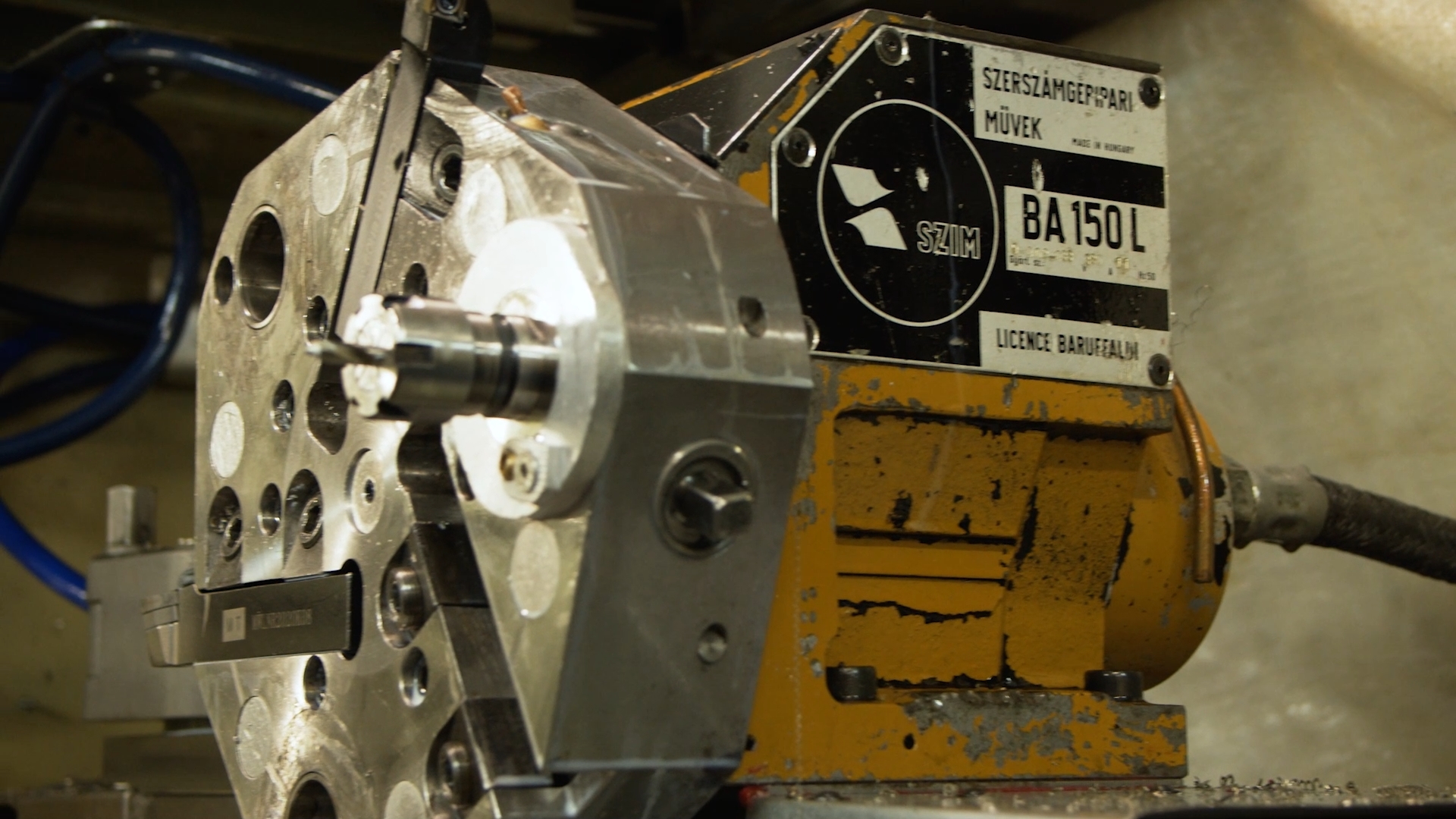
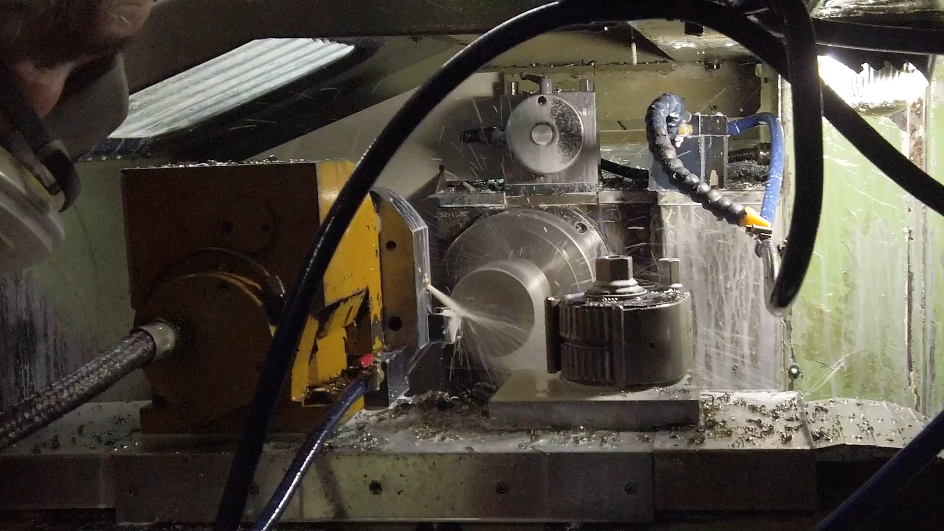
Unfortunately, our idea to fit the nozzle onto the pipe along the thread did not work – Kirill did not fit a pipe of this diameter into the cartridge. Well, let’s get back to the idea of putting the nozzle on a hot pipe, sealing it with a heat-resistant sealant, drilling and bolting, cutting a thread in the pipe body.
I would like to thank Uncle Kirill once again: thank you very much, you helped out a lot and told a lot!
Stand Electronics
Since mechanical scales were abandoned in favor of strain gauges, they began to dance from them. The question arose on the topic of presenting data in a form that is convenient for perception and analysis, and I would also like to abandon wires, as well as be able to initiate ignition from a shelter, at a distance, because safety is above all. In the end, we assembled the pipe and are going to fill it with a propellant charge.
So, the Wemos D1 R2 Mini board powered by ESP-12F was chosen as the brain for the stand. If someone is not in the know, this is a 32-bit controller with 4MB memory (the flash drive is soldered right on the debug board) and WIFI on board is what you need.

There will be two sensors on the stand, they are half-bridge, but we decided to connect them using a bridge circuit, which will give higher accuracy and allow us to increase the measurement limit to 100kg (two sensors 50kg each). It turned out here is such a mount. Uniform pressure will be achieved through the rocker arm.
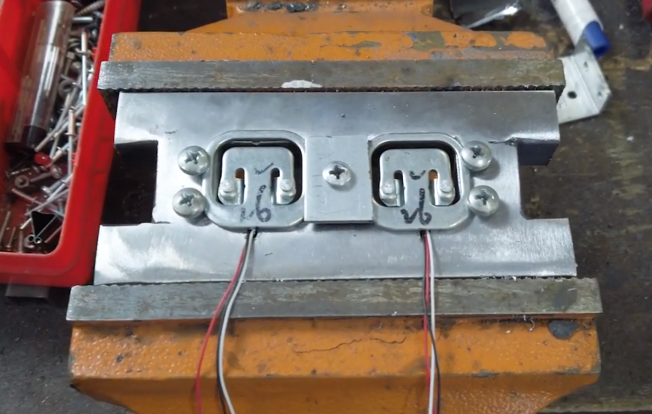
The sensors are interrogated by a module on the HX711 microcircuit. By default, the module is wired so that it gives a sampling frequency of 10Hz, but simply re-soldering the jumper resistor raises the frequency to 80Hz. The chronometers showed that it takes 11-12ms to get one value, let’s set a period of 15ms just in case, it comes out about 66Hz, which is quite acceptable.
Logging is carried out on the internal SPIFFS memory, which will allow you to pack files in a convenient format (in our case, txt), copy them to another medium and process them in external programs if desired.
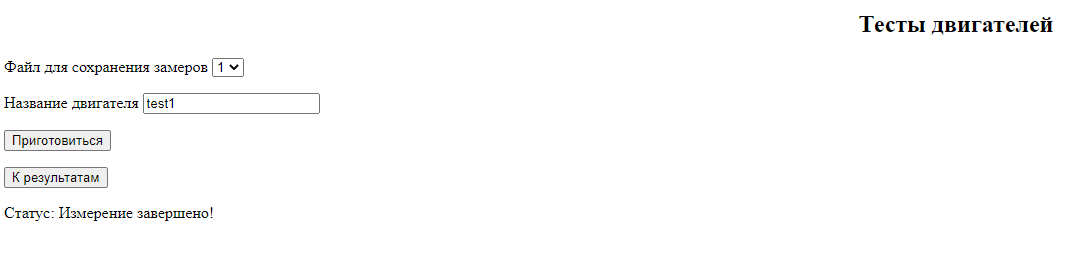
But I wanted clarity. Therefore, a web interface was written in which you can build graphs, see the thrust at each moment in time, as well as overlay graphs on top of each other and compare. If necessary, you can also disable unnecessary graphs. Made for comparison 6 motors for 20 seconds each, can be changed if desired. Links to the code will be at the end of the article. Let me remind you that in order to obtain correct data, the load cells must be calibrated before use. Calibration sketch included. There are many utility functions left in the sketch that may be useful.
I also want to remind you that the sketch uses the SPIFFS file system, I recommend it first familiarize with her work.
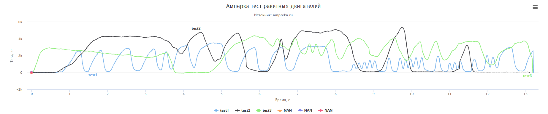
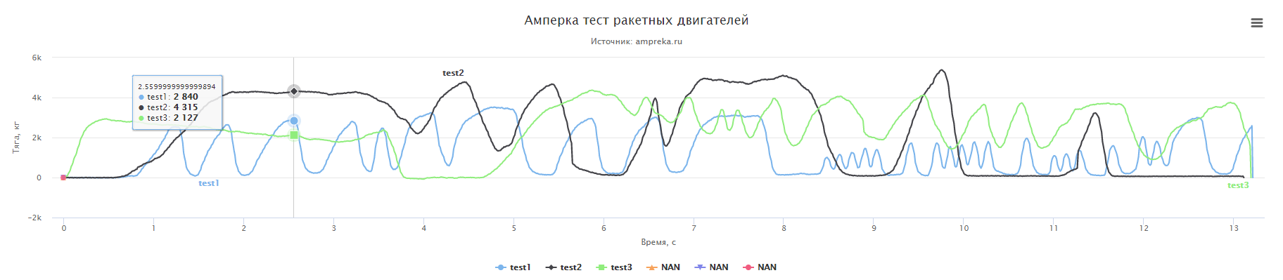
Blanks used for programming Sergei Tretyakov, the plotting script is taken from the site Highcharts…
When you press the start button, power will be supplied to the electric igniter through the mosfet, which initiates the ignition of the fuel.
Thus, we have everything ready for the fire tests, which we will conduct early next week, and on Saturday we will share the data and experience we have received.
Stay with us, there will be many more interesting things.
Links:
Calibration firmware
Charting firmware